


Controlling engine temperature, 5
Page 48
If you've noticed an error in this article please click here to report it so we can fix it.
IN THE LAST article on the control of engine temperature cooling fans which stop automatically, and those which run at reduced speeds, were discussed. Quenton HazeII has a completely different solution to the problem of matching the airflow from the fan with that required to maintain the correct engine temperature.
In its Thermofan, the pitch of the fan blades vary automatically so that the airflow from the fan suits the cooling requirements of the engine at all times. The fan is a modulating device which is sensitive to air temperature. It is a variable pitch fan which is permanently fastened to the vehicle water pump, by conventional mounting bolts.
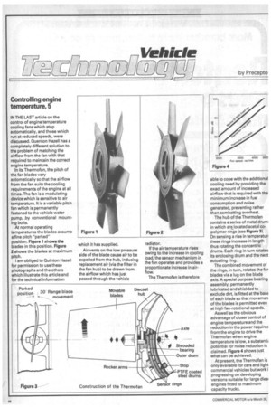
At normal operating temperatures the blades assume a fine pitch "parked" position. Figure 1 shows the blades in this position. Figure 2 shows the blades at maximum pitch.
I am obliged to Quinton Hazell for permission to use these photographs and the others which illustrate this article and for the technical information which it has supplied.
Air vents on the low pressure side of the blade cause air to be expelled from the hub, inducing replacement air (via the filter in the fan hub) to be drawn from the airflow which has just passed through the vehicle radiator.
If the air temperature rises owing to the increase in cooling load, the sensor mechanism in the fan operates and provides a proportionate increase in airflow.
The Thermofan is therefore able to cope with the additional cooling need by providing the exact amount of increased airflow that is required with the minimum increase in fuel consumption and noise generated, preventing rather than combatting overheat.
The hub of the Thermofan contains a series of metal drum: in which are located acetal copolymer rings (see Figure 3). On sensing a rise in temperatun these rings increase in length thus rotating the concentric drums. Each ring in turn rotates its enclosing drum and the next actuating ring.
The combined movement of the rings, in turn, rotates the far blades via a lug on the blade axis. A special purpose bearing assembly, permanently lubricated and shielded to exclude dirt, is fitted at the basE of each blade so that movemen of the blades is permitted even at high fan-rotational speeds.
As well as the obvious advantage of closer control of engine temperature and the reduction in the power requirec from the engine to drive the Thermofan when engine temperature is low, a substantii potential for noise reduction is claimed. Figure 4 shows just what can be achieved.
At present, the Thermofan is only available for cars and light commercial vehicles but work i progressing on developing versions suitable for large dies' engines fitted to maximum capacity trucks.