


The Borg-Warner Type 35 Automatic Transmission
Page 67
If you've noticed an error in this article please click here to report it so we can fix it.
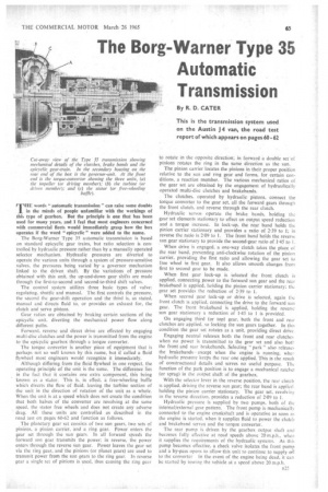
By R. D. CATER
THE words "automatic transmission" can raise some doubts in the minds of people unfamiliar with the workings of this type of gearbox. But the principle is one that has been used for many years, and I feel that most engineers concerned with commercial Beets would immediately grasp how the box operates if the word "epicyclic" were added to the name.
The Borg-Warner Type 35 automatic transmission is based on standard epicyclic gear trains, but ratio selection is controlled by hydraulic pressure rather than by a manually operated selector mechanism. Hydraulic pressures are diverted to operate the various units through a system of pressure-sensitive valves, the pressures being varied by a governor mechanism linked to the driven shaft. By the variations of pressure obtained with this unit, the up-and-down gear shifts are made through the first-to-second and second-to-third shift valves.
The control system utilizes three basic types of valve: regulating. shuttle and manual. The first controls the pressure, the second the gear-shift operation and the third is, as stated, manual and directs fluid to, or provides an exhaust for, the clutch and servo pistons.
Gear ratios are obtained by braking certain sections of the epicyclic unit, diverting the mechanical power flow along different paths.
Forward, reverse and direct drive are effected by engaging multi-disc clutches and the power is transmitted from the engine to the epicyclic gearbox through a torque converter.
The torque converter is another piece of equipment that is perhaps not so well known by this name, but if called a fluid flywheel most engineers would recognize it immediately.
Although differing from the fluid flywheel in one respect, the operating principle of the unit is the same. The difference lies in the fact that it contains one extra component, this being known as a stator. This is. in effect. a free-wheeling baffle which diverts the flow of fluid, leaving the turbine section of the unit in the direction of rotation of the unit as a whole. When the unit is at a speed which does not create the condition that both halves of the converter are revolving at the same speed, the stator free wheels and does not create any adverse drag. All these units are controlled as described in the road test on pages 60-62 and function as follows.
The planetary gear set consists of two sun gears, two sets of pinions. a pinion carrier, and a ring gear. Power enters the gear set through the sun gears. In all forward speeds the forward sun gear transmits the power; in reverse, the power enters through the reverse sun gear. Power leaves the gear set via the ring gear, and the pinions (or planet gears) are used to transmit power from the sun gears to the ring gear. In reverse gear a single set of pillions is used, thus causing the ring gear to rotate in the opposite direction; in forward a double set of pinions rotates the ring in the same direction as the sun.
The pinion carrier locates the pinions in their proper position relative to the sun and ring gear and forms, for certain conditions, a reaction member. The various mechanical ratios of the gear set are obtained by the engagement of hydraulically operated multi-disc clutches and brakebands.
The clutches, operated by hydraulic pistons, connect the torque converter to the gear set, all the forward gears through the front clutch, and reverse through the rear clutch.
Hydraulic servos operate the brake bands, holding the gear set elements stationary to effect an output speed reduction and a torque increase. In lock-up, the rear band holds the pinion carrier stationary and provides a ratio of 2-39 to 1; in reverse the ratio is 2-09 to L The front band holds the reverse sun gear stationary to provide the second-gear ratio of 1-45 to I.
When drive is engaged, a one-way clutch takes the place of the rear band, preventing anti-clockwise rotation of the pinion carrier, providing the first ratio and allowing the gear set to free wheel in first gear. It also allows smooth changes from first to second gear to be made.
When first gear lock-up is selected the front clutch is applied, connecting power to the forward sun gear and the rear brakeband is applied, holding the pinion carrier stationary; the gear set provides the reduction of 2-39 to 1.
When second gear lock-up or drive is selected, again the front clutch is applied, connecting the drive to the forward sun gear. The front brakeband is applied, holding the reverse sun gear stationary a reduction of 1-45 to 1 is provided.
On engaging third (or top) gear, both the front and rear clutches are applied. so locking the sun gears together. In this condition the gear set rotates as a unit, providing direct drive
Engaging neutral releases both the front and rear clutches when no power is transmitted to the gear set and also boll, the front and rear brakebands. Selecting " park" also releases the brakebands—except when the engine is running, when hydraulic pressure keeps the rear one applied. This is the result of constructional details arid serves no useful purpose. The function of the park position is to engage a mechanical ratchet (or sprag) in the output shaft of the gearbox.
With the selector lever in the reverse position, the rear clutch is applied, driving the reverse sun gear; the rear band is applied. holding the pinion carrier stationary. The gear set, revolving in the reverse direction, provides a reduction of 2-09 to 1.
Hydraulic pressure is supplied by two pumps. both of the internal/external gear pattern. The front pump is mechanically connected to the engine crankshaft and is operative as soon as the engine is started. when it supplies fluid to power the clutch and brakeband servos and the torque converter.
The rear pump is driven by the gearbox outpui shaft and becomes fully effective at road speeds above 20 m.p.h.. when it supplies the requirements of the hydraulic systems. As this pump becomes effective, a check valve isolates the front pump and a by-pass opens to allow this unit to continue to supply oil to the converter In the event of the engine being dead, it can be started by towing the vehicle at a speed above 20 m.p.h.