


A Flat-twin Two-stroke
Page 66
If you've noticed an error in this article please click here to report it so we can fix it.
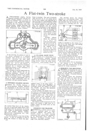
A TWO-STROKE engine, having rtopposed cylinders, but with the two pistons moving together, is shown in patent No. 775,78L The chief point of the patent is the method of counterbalancing the two pistons with other moving masses. (Regie Nationale des Usines Renault, 8/10 Avenue Emile Zola, Billancourt, Seine, France.)
In-the drawing, the pistons (1 and 2) are shown connected to a common crankpin, thus giving an even firing interval. However, the dual mass creates considerable unbalance which is only partially cancelled out by counterweights (3). As is well known, a reciprocating mass cannot be completely balanced by a rotating one, there remaining always a new unbalance at right-angles to the first.
The problem is solved ingeniously by using the Roots blower (4) as an opposing unbalance. Certain of the lobes are hollow (as shown at 5), whilst others are loaded as at 6. The masses can be accurately determined, and if driven in timed relationship with the crankshaft will give precise balance.
A POWERED LOADING DEVICE
PATENT No. 776,002 discloses a power-operated loading platform for attachment to the rear of a lorry. It is intended to operate not only from
the normal floor level of the vehicle, but also to and from higher floors, thus dispensing with the necessity of crating such things as Motorcycles, refrigerators and similar delicate articles. (Burtonwood Engineering Co., Ltd., Buttonwood, Lancs.)
The drawing shows a rear view of the device. A pair of uprights (I and 2) guide the runners to which the plat
a34 form is attached. The unit is hydraulically powered by an oil pump driven by the main engine, and operated by a ram (3) lying in a cross-member. Cables arc anchored at point 4, and after passing around pulleys at each end of the ram, run upwards into the vertical guides for attachment to the platform. The controls are close to the platform and overloading is prevented by a safety valve which is located in the hydraulic circuit.
Another scheme shows the inclusion of a pair of hydraulic jacks under the platform to relieve the springs of the vehicle f r o m some of the load, particularly when the imposed weight is in excess of a ton.
A CO-AXIAL GLOW PLUG THE location of a heater-plug in a -t pre-combustion chamber usually results in the symmetry of the chamber being broken where the plug enters; furthermore, water-cooling cannot be applied easily in the .plug region. A design in which these objections are overcome forms the subject of patent No. 774,948. (H. List, 126 Heinrichstrasse, (iraz, Austria.) In this scheme, the heater wire is in the form of a horizontal loop (1) which is embedded in a washer held down by a screwed sleeve (2). The washer is drilled radially and insulated at the point where the two leads (3) pass through the side. The insulation is, of necessity, gastight.
The injector itself is screwed into the sleeve and makes a tight joint an a copper washer (4) which seats on the heater washer.
STEERING FOR TRAILERS
REVERSING a vehicle and its trailer in a confined space is often extremely difficult, and patent No. 775,753 shows a trailer steering mechanism that enables the manceuvre to be performed more easily. (C. Wheatley, Northgate Cottage, Fontridge Lane, Burwash, Sussex.)
The drawing shows the scheme applied to a two-wheeled trailer. The trailer axle can swing about a centre pin .(1) and may be moved by a rod attached to a steering arm (2). The railer is attached to the tractor by a pin (3) in the usual way, and during towing behaves normally.
When the vehicle is to be reversed, a fulcrum pin for a lever (4) is placed in the hole 5. Then, the change in direction of the line of motion of the tractor moves a bellcrank (6) and a link (7) to actuate the turntable of the trailer in the required direction.
For forward running the lever can be fulcrummed about point 8. If this is done, the trailer will actively steer itself in the tractor path.
The patent shows also an adaptation of the scheme to a four-wheeled trailer, and such modifications as are required for brake actuation.
A RESILIENT CAB MOUNTING
AMETHOD of mounting the cab of a commercial vehicle in a resilient manner on the chassis is disclosed in patent No. 775,604. (Vauxhall Motors, Ltd., Luton, Beds.) The drawing shows the mounting unit, three of which are used, two at the front and one at the rear of the cab: To the centre •of a chassis crossmember (1) is secured a U-bracket (2) through which a pin (3) is placed and held by a nut at each end.
To a cross-bearer of the cab is welded a bush (4) having a bell-mouthed bore. A pair of metal-sleeved rubber bushes (5) are inserted between the bush and pin, and these form the resilient members. They are compressed during assembly by concave end-washers. One end-plate (6) is detachable for reasons of assembly.