


Front-wheel-drive Transmission System
Page 58
If you've noticed an error in this article please click here to report it so we can fix it.
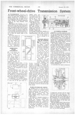
A TRANSMISSION layout for rt vehicles having front-wheel drive is shown in patent No. 647,010, by L. Billotti, Turin, Italy. Its chief features are compactness and its ability to provide a measure of torsional cushioning owing to the long propeller shaft employed.
Referring to the drawing, I is thc clutch and 2 the axis of the half-shafts. The-drive is taken from the clutch by a Ibng, torsionally resilient shaft (3) which extendsto the far end of the gearbox, where it carries the primary pinion (4). A Substantially conventional gearbox is used, except that the main shaft is tubular to allow the smaller shaft to pass through it.
The bevel pinion (5) and its crown-wheel (6) are of the hypoid type. so that the half-shafts may pass beneath the drive shaft. The halfshafts are fitted with external universal joints so that independent suspension can be used.
DISSIPATING STATIC ELECTRICITY IT is well known that
on a hot, dry day a running vehicle can build up a powerful static charge owing to the insulating effect of its rubber tyres, and it is possible that an alighting passenger can receive quite a nasty shock. It may be remembered that steam wagons used to trail a short length of chain to disperse the charge as it formed, but this solution is not acceptable by presentday standards.
Electro-conductive tyres have also been tried, but they have not proved entirely satisfactory. A much more simple solution is put forward in patent No. 646,679, by J. Collins and the Firestone Tyre and Rubber Co., Ltd., Great West Road, Brentford, Middlesex.
As dampness is an excellent preenfive of the phenomenon, it is proposed to keep one of the tyre walls in a slightly moist state. To provide the necessary water-vapour, the exhaust gas is used; this, of course, contains a considerable percentage of water.
The drawing shows a specimen layout in which the exhaust is first taken through a silencer (I) fitted with cooling fins, and then through a finned pipe (2), the gases being final y ejected on to the side of one of the tyres. It is considered desirable to fit some form of oilfilter in the system to prevent damage to the tyre. 646,679 QUICKER PICK-UP FOR OIL ENGINES
WITH an oil engine it W may happen that too sudden a throttle opening may produce a temporary weakening of the fuel-air ratio before the suction reaches its normal value. To prevent this is the aim of a refinement in the control system shown in patent No. 643,246, by C.A.V., Ltd., Warple Way, London, W3.
Referring to the drawing, 1 is the injection pump and 2 the air intake complete with throttle. Connected to the intake is a chamber containing a flexible diaphragm (3) provided with a small leakorifice through it. In normal operation the diaphragm does not move, because the leak ensures a pressure balance between the upper and lower chambers.
But should the throttle be suddenly opened, the diaphragm is momentarily sucked upwards and closes a pair of switch contacts (4). This closes a circuit which energizes a solenoid (5) which then pulls the rack-rod of the pump into the open position and gives, an
increased fuel injection. A one-way valve in the centre of the diaphragm prevents the device moving in the.opposite direction should the throttle be suddenly closed.
RADIO-CONTROLLED POINTS
A RADIO system by which the driver
of a vehicle can remotely control devices along the track, is shown in patent No. 642,641, by Jackson Automatic Electric Controls. Ltd., and others, Windsor House, Victoria Street, London, S.W.I.
The scheme is intended primarily to enable the driver of a trolleybus to operate the overhead points when approaching a junction. Instead of stopping and leaving the vehicle to do this, he can set the points in advance. A short-range transmitter is carried on the vehicle; this operates a receiver which works, via a relay, the points mechanism. AN INERTIA STARTER
OW1NG to its high compression ratio. the oil engine calls for considerable starting effort, and this, if it has to hc applied manually, almost reaches the limit of human power. A new approach to the problem is shown in patent No. 646,336, by V. Pilkington and Leyland Motors, Ltd., Suffolk House, Laurence Pountney Hill, London, E.C.4.
The scheme employs an additional' geared-up flywheel which is accelerated by hand, the energy thus stored being applied to the crankshaft to help to overcome the first compression. The drawing shows the complete unit. which is intended to he attached to the front-end of the crankcase.
An. extension (I) of the crankshaft. carries at its outermost end a free wheel (2) the pawls of which engage a ratchetwheel cut on a free sleeve (3). This sleeve carries a sprocket, the chain (41 from which is connected with the starting-handle. On this ' same sleeve is also. a spur-gear (5) driving, via double speed-increasing gears (6) the auxiliary flywheel (7). In operation, the engine compression
is temporarily released, and the engine rotated by hand in the usual way. This also turns the auxiliary flywheel at a speed of from four to ten times that of the crankshaft. As soon as the compression is restored, it is overcome by the total stored energy of the main and auxiliary flywheels.
Once the engine starts, it can overrun on account of the free-wheel, the pawls of which are then lifted by centrifugal force, so that no continuous clicking sound is produced and unnecessary wear on The pawls prevented.