


UNIVERSAL JOINTS IN THEORY AND PRACTICE.
Page 25
Page 26
If you've noticed an error in this article please click here to report it so we can fix it.
The Advantages and Disadvantages of Various Types from the User's Point of View.
IN almost every orthodox petrol-driven chassis the transmission embodies two or mare universal
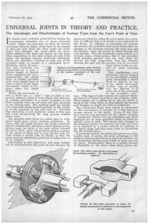
• joints. These are provided to allow 6f relative movement between shafts which have to be coupled so that one may drive the, other under all conditions. For example, the worm shaft (or bevelpinion shaft) in the back axle moves up and down" when inequalities in the road surface are met with, whilst the gearbox remains relatively stationary. Joints are, therefore, required at each end of the propeller shaft, topermit of a continuous drive. Similarly, unless the gear.. box and crankcase are Points in the constructed as a unit, a and universal certain length of flexible IL to the relativ frame separates the two ; consequently, the clutch shaft is usually provided with some simple form of joint to allow -of the small movements which t ake place when the frame deflects.
Where the movement is only a small one, a " gear " type of joint is frequently adopted, which is both simple and effective. It consists essentially of a pinion mounted on the shaft meshing with an internally cut gear mounted on the driving part. The meshing teeth are usually well protected, being housed partially in the clutch, or in the gearbox, as the case may be. Provided that lubrication is not neglected, joints of this type will work satisfactorily for long periods without undue wear.
The propeller-shaft joints are called upon to withstand much more severe working conditions. To begin with, the angle between the shafts connected may be considerable, and this in itself imposes severe strains upon the parts of the joint which transmit the drive. Then, again, the propeller shaft is exposed to the action of damp and to mud thrown from tti: road (unless a torque tube be fitted), so that the joints must be adequately protected if undue wear is to be avoided.
Lubrication is also important, and some designs can be criticised from this point of view, because the
SEMI-FLEX IEN.E JOINTS ALLOWING FOE MAL-ALIGNMENT
means provided for oiling the parts make this opera,. tion so difficult that it is bound to be neglected by the driver. In addition to providing for angular movements, the propeller-shaft joints must allow for changes in the distance between the bank axle and the gearbox, when the torque is taken throughthe rear springs. The axle frequently moves almost in a vertical plane, which means that if the propeller shaft becomes parallel with the road when the springs are fully compressed, then the distance between the axle and the gearbox will be increased when lighter loads are carried or when bouncing occurs.
This lengthening a n d shortening can be allowed for by providing a sliding joint, comprising a sleeve fitted to splines, on one of the shafts concerned. Another way of getting over the difficulty is to make one of the universals of the so-called " pot" type. This type of joint consists of a pair of blocks pivoted to a T-piece secured to the propeller shaft. These blocks are a sliding fit in the pot which is fitted to the worm shaft, so that angular movements and 'changes in length are both Provided for.
The well-known fabric joint should be mentioned in this connection ; it consists of a ring bolted to prongs secured to the shafts. Joints of this type have proved very successful for_the lighter varieties of commercial vehicle, but one sometimes sees them employed for an open propeller shaft, in which no slidable joint is used. This means that changes in the distance between the gearbox and back axle have to be absorbed by a certain amount of buckling in the fabric rings, and this must result in shortening the life of these parts.
If properly treated, the fabric joint gives very little trouble, and, of course, the great advantage of the design is that no lubrication is required, as there are no mechanical bearing parts liable to wear and set up rattle. Furthermore, there is a certain amount of flexibility in the drive when fabric joints are transmission where flexible joints are necessary, owing e movement of the cornponents.
UNIVEILIAL JOINTS ALLOWING FOR AXLE MOVEMENTS
used, which reduces the shocksto the final drive. One of the reasons why this type of joint is not adopted to a wider extent on heavy vehicles is, no doubt, found in the fact that large, transmission brakes are frequently fitted. If the driver declutches, and then applies the transmission brake violently, the stress on the joint is suddenly reversed, and this, of course, tends to tear the fabric ring. ,
Reverting to mechanical joints, the old and well
tried Hooke type is still very popular. This consists, essentially, of a. cruciform member pivoted to forks, one of -which is secured to each of the shafts. There are four load-carrying bearings, which must be protected from dirt and must be adequately lubricated if excessive wear is to be prevented. The obvious method for reducing the load on the bearings is to increase the size of the joint, but there are definite limits to the dimensions which can be used. In addition, increasing the size likewise increases the amount of rubbing between each bearing and its journal. A fairly satisfactory compromise is usually decided upon by designers, and good results are obtained, provided that the lubrication and protection are adequate.
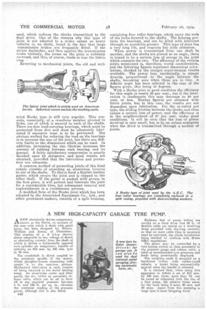
A common method of protecting joints of this kind simply consists of attaching an aluminium housing to one of the shafts. To this is fixed a flexible leather gaiter, which covers the joint and is clipped to the other shaft. If the gaiter is packed with grease in the first place, it will protect and lubricate the joint for a considerable time, but subsequent removal and replenishment is a troublesome process.
A modified form of the Hooke joint which has been adopted by the Associated Equipment Co., Ltd., and other prominent makers, consists of a split housing, containing four roller bearings, which carry the ends of the forks Aecured to the shafts. The housing protects the bearings, and can be filled with lubricant through an acce.ssible greaser. This type of joint has a very long life, and requires but little attention.
When .power is transmitted from one shaft to another, and the shafts are placed at an angle, there is bound to be a certain loss of energy in the joint which connects the two. The efficiency of the various joints mentioned is, therefore, worth consideration, and -the following figures represent theoretical calculations, checked by the meagre experimental results available. The power loss, incidentally, is almost directly • proportional . to the angle between the shafts, becoming zero when these are in line. A definite angle has been selected in the ease of the figures given, this being 10 degrees.
With a Hooke joint in good condition the efficiency for this angle is nearly 99 per cent., but if the lubrication is inadequate this may decrease to 90 per cent. or less. Similar figures are obtained with fabric joints, but in this case the results are not dependent upon lubrication. For the so-called pot type, the sliding friction between the blocks and slots causes a certain loss of power, and the efficiency is in the neighbourhood of 97 per cent. under good conditions. It will be seen that the loss of power involved is only small, but is by no means.negligible when the drive is transmitted' through a number of joints.