


Ingenious Excess-fuel C.I. Engine Starting Device
Page 36
If you've noticed an error in this article please click here to report it so we can fix it.
A SCHEME for facili/-1 tating the starting of oil engines comes in patent No. 540,788, from John I. Thornycroff and Co., Ltd., and W. Deck, both of Smith Square, London, S.W.I. The patent states, in a preamble, that as most commercialvehicle makers buy their injection -pumps more or less ready-made, it is hardly practicable to effect any alterations to the pump itself, and individual requirements must be achieved externally of the pump. The patent shows this vehicle maker's own scheme for controlling excess fuel delivery.
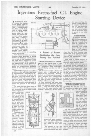
In the diagram is seen a conventional injection pump, governed by engine suction, the diaphragm (4) being open on one side to the atmosphere, whilst the other side is subject to, suction created on a nozzle (8) in a venturi in the engine intake. So far operation is normal, the fuel quantity being con trolled by induction-pipe depression varied by the pedal-operated throttle valve.
The excess-fuel supply is arranged fora
as follows:—The rack-rod of the pump is associated with a full-load stop (5),
but this is connected, via a lever (6) and a rod (7) to the throttle valve, so that it is moved to the excess-fuel posi tion only when the accelerator pedal (3) is released. When the driver depresses the pedal, its first action is to restore the position of the fall-load stop.
This means that the engine must be started on a closed throttle, a condition not favourable to an oil engine, which needs a copious air supply at thisetime. To provide for this, an air-valve (2) is fitted on the induction pipe, and is manually opened when the engine is to be started. Should the driver accidentally leave it open, it will be flicked into the closed position by projection 1.
The scheme completely prevents the driver from misusing the overinjection system for extra power during hill-climbing, as it can be brought into action only by a closed throttle and absence of suction. A WELL-DESIGNED GAS FILTER
DATENT No. 531,795, from S. Alley
and Sentinel Waggon Works (1936), Ltd., Shrewsbury, shows a gas-cleansing and filtering unit for use with a producer.
The device is housed in a sheet-sr.,:tal cylinder with a detkhable lid for removal of the filter units. Actually, the body is divided into two compartments, separated by a clamped-down ring (3). Gas enters tangentially via pipe 5 and is spread around the cylinder by a deflector vane (6).
It then penetrates the inner filter (1) which consists of a hollow cylinder faced with coconut matting and wire gauze. From the inside of this gas passes into the upper chamber and traverses a packing (I) of sisal tow or
sponge-cloth under compresOon. This removes the finest of the impurities, and the gas then makes an exit from pipe 8.
By removal of the top cover the packing (1) can easily be drawn out, and then, by unscrewing the spindle (7) and removing it complete with its nutbar (2), the lower filter can be withdrawn. The bar (2) is fitted with a species of bayonet fixing to permit of easy withdrawal.
GAS-PRODUCER WARNING DEVICE WHEN the quantity of W fuel in a gas producer falls to a certain level there is a possibility of the combustion zone spreading, with consequent damage to the walls of the producer. To indicate to the driver when the fuel level becomes dangerously low is the object of a device shown in patent No. 540,295 by Societe Nouvelle des Automobiles " Unic," Puteaux, Seine, France.
Some form of remote warning is obviously necessary and, in this case, electricity is the operating means.
In the wall (1) of the fuel hopper is an inserted switch consisting of a pivoted plate (5), which is subjected to the weight of the fuel above it. When loaded, the plate is held down against its spring on to a stop (4), but when the fuel level sinks below the plate it can be lifted by its spring and allows a hook (3) to make contact with an insulated terminal (2). This operates a lamp or buzzer in the cab, which draws the driver's attention to the need for more fuel.
LOCK-NUT INCORPORATING THREAD-GRIPPING CHUCK
DATENT No. 540,864 comes from
specialists in small parts, Tecale mit, Ltd., and T. W. Langley, both of Great West Road, Brentford, and discloses a design for a cheap and simple vibration proof nut, which can be reused an indefinite number of times, and can be freely run on or off its bolt without the use of a spanner.
, The nut is of standard dimensions, but has machined in its base a conical sided annular groove (3). An L-section dished spring-washer (2) is used under the nut, and partly enters the groove, as shown. When the nut is tightened, the flattening of the dished portion
forces the upper part into the groove,
so that it exerts an inward force on the cone (1) formed in the nut and causes a chuck-like grip on the bolt. The rim (1) has a number of radial sawcuts, which allow it to contract and expand.