


Patents Completed.
Page 22
If you've noticed an error in this article please click here to report it so we can fix it.
T. CROSBR2 AND SONS., LTD., and D. 31cGRER0R, No. 19,886„ dated 17th September, 1914.—In this sparking plug mica washers are used to form the main body of the insulator.
The central electrode first had a mica tube threaded on to
it, and then outside this a set of washers to fill no the interior of the shell of the plug. A copper or asbestos washer is inserted between the mica and the internal shoulder on the shell. Smaller washers are used near the top, and these are all pressed tightly together by nuts threaded on the stem.
These nuts and the small mica washers are surrounded by a set of large mica washers, which are compressed and have their outer surfane turned and polished. • A. feature of the present invention lies in the construction of the plug, so that there is no fear of any of the engine compression escaping.
G. MILLER, No. 20,882, dated 12th October, 1914.—In this wheel the felloe is slotted opposite each spoke, and a U-shaped bracket lies in the slot. The 'brackets are = all retained in position by a .binding, ring surrounding them. The tread is supported by. two side members which are bolted together, one of them having a circumferential plate, on which the tread is seated.
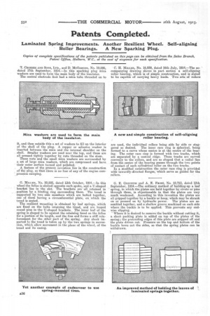
• The resilient mounting is obtained by leaf springs, which are fixed on the bolts retaining the tread, and are looped round pins in-the.U-shaped brackets. The inner leaf of the spring is shaped to lie against the retaining hand on the felloe for a portion of its length, and the free end forms a stiff reinforcement. for the other part of the spring. Any shock imparted to the tread is taken up by the two springs in succession, which allow movement in the plane of the wheel, of the tread and its casing. C. H. 11/1ELER, No. 16,939, dated 16th July, 1914.—The accompanying drawing shows in part section a self-aligning roller bearing, which is of simple construction, and is stated to be capable of carrying heavy loads. Two sets of rollers
are used, the individual rollers being side by side or stag
gered as desired. The inner race ring is spherical, being formed to a curve whose centre is at the centre of the bearing. The outer race ring is formed with two tracks, which are separated by a central ridge. These tracks are curved convexly to the rollers and are so shaped that a radial line from the centre of the bearing passes through the two points of contact of each cylindrical roller on the two tracks.
In a modified construction the outer race ring is provided with inwardly-directed flanges, which serve as guides for the rollers.
G. E. GnivFmt and A. E. FROST, No. 19,715, dated 12th September, 1914.—The ordinary method of building-up a leaf spring, in which the plates are held together by-rivets or pins through them, is objectionable in that the plates are very much weakened. According to this invention the plates are all gripped together by a buckle' or hciop; which may be shrunk on or pressed on by hydraulic power. The' plates are assembled together, and a shallow groove machined on each side where. the buckle is to be applied. This prevents any endwise slipping.
• Where it is desired to remove the buckle without cutting it, a short packing plate is added on top of the plates of the spring; the protruding edges of this plate are snipped off and the plate driven out; Presaure on the top and bottom of the buckle bows out the sides, so that the spring plates can be withdrawn.