


MAKING BEST USE OF THE FORD.
Page 51
If you've noticed an error in this article please click here to report it so we can fix it.
Valuable Advice on Every Phase of Ford Transport which will Appeal to the Owner, Driver and Repairer. ,
499.—A Useful Pair of Chassis Supports.
Unless equipped with special Fordchassis lifting irons and pulley blocks, the removal of a front or rear axle for repair causes a certain amount of difficulty in adequately supporting the chassis during the operation, the usual method being to carry the chassis more or less rigidly on ebeh side by means of jacks mounted on sundry blocks. This cannot be regarded as Ideal by a long way. It takes time to sort out the necessary blocks and to erect them, and the chassis is even theu not rigid, swaying perilously at the slightest touch.
In the garage where the special lifting gear is not available a very useful. substitute can be easily built up in
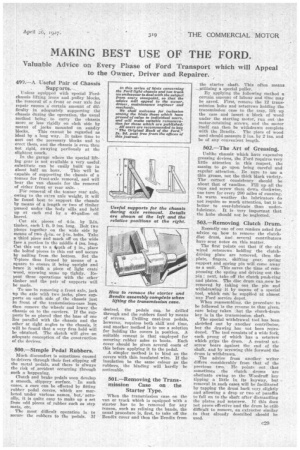
about half an hour. This will be capable of supporting the chassis of a twiner for front-axle removal, and will hear the van ehassis for the removal of either front or rear axle.
For removal of the tonner rear axle, owing to the extra axle weight, it will be found best to support the chassis by means of a length or two of timber passed under the body sills and held up at each end by a 40-gallon oil barrel.
Cut six pieces of 4-in. by 2ein. timber, each 1 ft. 9 ins. long. Bolt two pieces together on the wide side by means of two-756-in. or a-in. bolts. Take a third piece and mark off on the wide face a portion in the middle 4 ins. long. Cut this out to a ot pth of A in., place the bolted pieces in this cut and secure by nailing from the bottom. Set the T-piece thus formed by means of a square to ensure it being upright and brace it with a piece of light crate wood, screwing same up tightly. Repeat these operations with the other timber and the pair of supports will be made.
To use in removing a front axle, jack tip the axle with two jacks, place supports on each side gf the chassis just in front of the transmission-case lugs, then remove the wheels and lower the chassis on to the carriers. If the supports be so placed that the base of one lies parallel with the chassis and the other at right angles to the chassis, it will he found that a very firm hold will be obtained. The sketch will give an adequate conception of the construction
of the devioes.
500.—Simple Pedal Rubbers.
Much discomfort is sometimes caused to drivers through their feet slipping off the metal pedals, and there is always the risk of _accident occurring through such a happening. Clutch and brae pedals soon develop a smooth, slippery surface. • In such cases, a Cure can be effected by fitting rubber pedal covers, which are marketed under various names, but,/actually, it is quite easy to make up a set from odd pieces of rubber such as step mats, etc.
The most difficult operation is to secure the rubbers to the pedals. If desired, the pedals can, be drilled through and the rubbers fixed by means of screws. Drilling cast-iron pedals, however, requires both skill and time, and another method is to use a solution for holding the covers in position. A suitable cement is that employed for securing rubber soles to boots. Each cover should be given several coats of this before applying it to the pedal.
A simpler method is to bind on the covers with thin insulated wire. If the insulation be the same colour as the rubbers, the binding will hardly be noticeable.
501.—Removing the Transmission Case on. the Starter Type.
'When the transmission case on the van or truck which is equipped with a starter has to be removed for any reason, such as relining the bands, the usual procedure is, first, to take off the Bendix cover and then the Bendix from
the starter shaft. This often means, _utilizing a special puller.
By applying the following method a certain amount of labour and titne may be saved, First, remove the 12 transmission bolts and setscrews holding the transmission case to the tray, lift up the case and insert a block of wood under the starting motor, run out the motor-retaining screws, and the motor itself can then be withdrawn complete with the Bendix. The piece of wood used should measure 2 ins. by 2 ins, and be of any convenient length.
502.—The Art of Greasing.
Unlike chassis which have expensive greasing devices, the Ford requires very little attention in this respect, the maxim to go upon being careful and regular attention. Be sure to use a thin "grease, not the thick black variety. The correct consistency should be about that of vaseline. Fill up all the cups and screw them down clockwise, one turn for every 200 miles of running. In warm weather the lubricators do not require so much attention, but it is better to over-lubricate than under. lubricate. It is very important that the hubs should not be neglected.
503.—Removing Clutch Drum.
Recently one of our readers asked for advice on how to remove the clutchdisc drum, and several contributors have sent notes on this matter.
The first points out that if the six wired setscrews holding the clutch'driving plate are removed, then the plate, fingers, shifting gear, spring support and spring pin will come away as a unit. This saves the time of compressing the spring and driving out the pin ; next, take off the clutch push-ring and plates. The disc drum can now be removed by taking out the pin and withdrawing it by means of a special tool, which can be supplied at almost any Ford service depot.
When reassembling, the procedure to be followed is the reverse to that given, care being taken :hat the clutch-drum key is in the transmission shaft.
The special withdrawal tool has been sketched out by another contributor, but the drawing has not been reproduced. The tool consists of a wide fork, each, prong of which has a setscrew which grips the drum. A. central setscrew bears against the end of the shaft, and by screwing this forward the drum is withdrawn.
The advice from another writer differs considerably from that of the previous two. He points out that sometimes the clutch drums are obstinate owing to the Woodruff key tipping a little in its keyway, but removal in such cases will he facilitated by tapping the drum back very slightly and allowing a drop or two of paraffin to fall on to the shaft after dismantling the plates and setscrew. If this does not prove effective and the drum he still. difficult to remove, an extractor similar to that already described should be used.