


From the
Page 34
Page 35
If you've noticed an error in this article please click here to report it so we can fix it.
ALTHOUGH diesel engineers have always strived for good fuel economy, it is only in the last few years that they have gone back to the first principles and looked at the various gas cycles and how they can be adopted for use with a diesel engine.
The compression ignition engine is by far the most fuel efficient power unit on the market, but with an overall efficiency of around 40 per cent plenty of room is left for improvement.
One interesting line of development is being carried out by Renault, utilising the principle of steam-engine operation to provide extra power at the crankshaft of a diesel engine.
The theoretical cycle on which the steam engine operates is known as the Rankine cycle. It differs from the air cycles in that the working substance changes its state during the cycle by evaporation and condensation; this working substance must therefore be a vapour.
In a steam engine all the operations of the Rankine cycle do not take place in the cylinder. The water is heated in the boiler, then expanded in the engine cylinder, finally condensed in the condenser; the hot water obtained from the condensed steam is then returned to the boiler.
With the internal combustion engine, a large portion of the available energy of the fuel is lost via the exhaust gases. Although the turbocharger makes some use of the exhaust energy, other ways of recovering waste heat are being investigated with enthusiasm and investment and many engineers are looking at the Rankine cycle in this context.
The cycle, or organic Rankine bottoming cycle, to give it its full automotive definition, is thought by many to offer the best potential for converting this waste energy energy into useable power at the crankshaft.
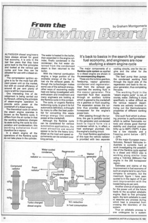
Although the Rankine cycle can be considered for various automotive applications, the most attractive use would appear to be for the heavy lorry diesel as the load and speed requirements can be constant over long periods. The major components of a Rankine cycle system as applied to a diesel engine are shown in the accompanying diagram.
These are the turbine gearbox, feedpump, vapour generator, condenser and regenerator. Heat from the exhaust gas vaporises the working fluid in the vapour generator. This vaporised fluid then expands through an auxiliary turbine which is geared to the crankshaft via a gearbox or fluid coupling. The expansion across the turbine thus provides additional horsepower for the engine's power train.
After passing through the turbine, the gas is partially cooled in the generator and condensed back to liquid form via a condenser which is, in effect, a heat exchanger plumbed into the engine's cooling circuit.
For most Rankine applications of this type the vehicle radiator is provided with two separate cooling circuits, one for the engine and the other for the condenser.
The feed pump then pumps the condensed working fluid through the liquid side of the regenerator and back to the vapour generator, thus completing the cycle.
The working fluid in the "steam engine cycle" is not, of course, water. Defining it more specifically is rather difficult as the various research departments are actively involved in trying out the thermodynamic properties of different working fluids.
One such fluid which is showing promise is perfluorohexane which is neither flammable nor toxic and shows good thermal stability and chemical compatibility up to 400°C (750°F). It also has a low viscosity and a freezing point below —30°C (-22°F).
Of the major European manufacturers, Renault Vehicules Industriels is currently hard at work investigating the possibilities of the Rankine cycle applied to a diesel and IVECO also is working along similar lines using a 13.8-litre (840cuin) Fiat engine in the 200 horsepower region.
Estimates and claims of the improvement in fuel economy of such an engine tend to vary from company to company, but the maximum figure I have seen quoted is in the region of 15 per cent improvement with the lowest being six per cent.
Another avenue of exploration for the power unit of the future leads to the so-called adiabatic engine. Back to first principles again, the term adiabatic is used to describe any process during which heat is prevented from crossing the boundary of the system.
Thus an adiabatic process is one undergone by a system which is thermally insulated 'rom its surroundings. In practi;al terms, this adiabatic expanlion may take place in the enOne cylinder in which case no leat passes through the cylinder walls for example and work is one on the piston as the gas axpands.
Again, many research and development departments are working on the adiabatic concept, including Leyland, Cummins, DAF and RVI. Leyland works to a heat balance where 36 per cent of the available energy from the fuel is converted to useful power at the crankshaft; 22 per cent goes into the coolant and 42 per cent is accounted for by the exhaust and the power required to drive engine auxiliaries.
Leyland research is aimed at developing an insulated engine where this 22 per cent heat-tocoolant figure is reduced to 14 per cent. This eight per cent heat "saving" has to go somewhere and most of it goes into the exhaust where it is more easily re coverable, eg by the turbocharger.
Leyland research on heat losses has gone into much finer detail on just where the heat goes to in a typical engine. It has been found that six per cent goes down the piston, six per cent through the liner with a further six to eight per cent going into the head either directly through the flame face or through the exhaust port.
According to Leyland, one approach to reducing heat to coolant is a minimally cooled cylinder head where the traditional water jacket is removed and replaced with precision cooling of the value bridge and injectors by means of drillings which give a directed flow of water. This move is predicted to give a further small reduction in heat loss-to-coolant of between two to four per cent.
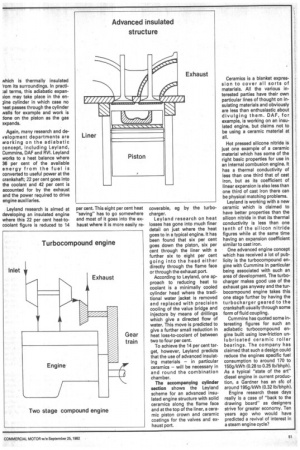
To achieve the 14 per cent target, however, Leyland predicts that the use of advanced insulating materials — in particular ceramics — will be necessary in and round the combination chamber.
The accompanying cylinder section shows the Leyland scheme for an advanced insulated engine structure with solid ceramics along the flame face and at the top of the liner, a ceramic piston crown and ceramic coatings for the valves and exhaust port. Ceramics is a blanket expression to cover all sorts of materials. All the various interested parties have their own particular lines of thought on insulating materials and obviously are less than enthusiastic about divulging them. DAF, for example, is working on an insulated engine, but claims not to be using a ceramic material at all.
Hot pressed silicone nitride is just one example of a ceramic material which has some of the right basic properties for use in an internal combusion engine. It has a thermal conductivity of less than one third that of cast iron, but as its coefficient of linear expansion is also less than one third of cast iron there can be physical matching problems.
Leyland is working with a new ceramic which is claimed to have better properties than the silicon nitride in that its thermal conductivity is less than one tenth of the silicon nitride figures while at the same time having an expansion coefficient similar to cast iron.
One advanced engine concept which has received a lot of publicity is the turbocompound engine with Cummins in particular being associated with such an area of development. The turbocharger makes good use of the exhaust gas anyway and the turbocompound engine takes this one stage further by having the turbocharger geared to the crankshaft usually through some form of fluid coupling.
Cummins has quoted some interesting figures for such an adiabatic turbocompound engine built using low-friction unlubricated ceramic roller bearings. The company has claimed that such a design could reduce the engines specific fuel consumption to around 170 to 150g/kWh (0.28 to 0.25 lb/bhph). As a typical "state of the art" diesel engine in current production, a Gardner has an sfc of around 195g/kWh (0.32 lb/bhph).
Engine research these days really is a case of "back to the drawing board" as designers strive for greater economy, Ten years ago who would have predicted a revival of interest in a steam engine cycle?