


Opposed-piston Two-stroke Engine
Page 80
If you've noticed an error in this article please click here to report it so we can fix it.
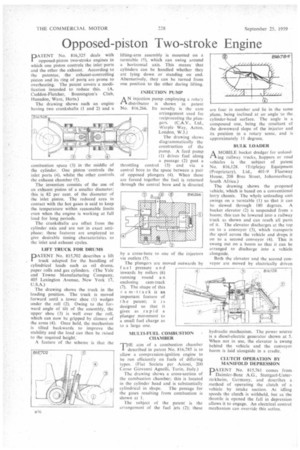
PATENT No. 816,325 deals with opposed-piston two-stroke engines in which one piston controls the inlet. ports and the other the exhaust. According to the patentee, the exhaust-controlling piston and its ring of ports are prone to overheating. The patent covers a modification intended to reduce this. (A. Cuddon-Fletcher, Bonnington's Club, Hunsdon, Ware, Herts.)
The drawing showssuch an engine having two crankshafts (1 and 2) and a combustion space (3) in the middle of the cylinder. One piston 'controls the inlet ports (4), whilst the other controls the exhaust chamber (5).
The invention consists of the use of an exhaust piston of a smaller diameter; this is 82 per cent, of the diameter of the inlet piston. The reduced area in contact with the hot gases is said to keep the temperature within reasonable limits even when the engine is working at full load for long periods.
The crankshafts are offset from the cylinder axis and are not in exact antiphase; these features are employed to give desirable timing characteristics to the inlet and exhaust cycles.
LIFT TRUCK FOR DRUMS
PATENT No. 815,702 describes a lift truck adapted for the handling of cylindrical loads such as oil drums, paper rolls and gas cylinders. (The Yale and Towne Manufacturing Company, 405 Lexington Avenue, New York 17, U.S.A.) The drawing shows the truck in the loading position. The truck is moved forward until a lower shoe (I) wedges under the roll (2). Owing to the for, ward angle of tilt of the assembly, the upper shoe (3) is well over the roll, which can now be gripped by closure of the arms (4). Once held, the mechanism is tilted backwards to improve the stability and the load can then be raised to the required height:
A feature of the scheme is that the lifting-arm assembly is mounted on a turntable (5). which can swing around a horizontal axis. This means that cylinders can be handled whether they are lying down or standing on end. Alternatively, they can be turned from one position to the other during lifting.
INJECTION PUMP
A N injection pump employing a rotary
distributor is shown in patent No. 816,266. Its novelty is the cam arrangement used for reciprocating the plungers. (C.A.V., Ltd., Warple Way, Acton, London, W.3.) The drawing shows diagrammatically the construction of the pump. A feed pump (1) drives fuel along a passage (2) past a throttling control (3) and via a central bore to the space between a pair of opposed plungers (4). When these are forced together the fuel is returned through the central bore and is directed.
by a cross-bore via outlets (5). to one of the injectors
The plungers are moved fuel pressure and inwards by rollers (6) running round a n enclosing cam-track (7). The shape of this 47 a m-track is an important feature of the patent; it is designed so that it gives as .rapid a plunger movement to a small fuel charge as to a large one.
MULTI-FUEL COMBUSTION CHAMBER
TJ-IE aim of a combustion chamber described in patent No. 816,785 is to allow a compression-ignition engine to be run efficiently on fuels of differing types. (Fiat Societa per Azioni, 200 Corso Giovanni Agnelli, Turin, Italy.) The drawing shows a cross-section of the combustion chamber; this is located in the cylinder head and is substantially cylindrical in shape. The passage for the gases resulting from combustion is shown at I.
The subject of the patent is the arrangement of the fuel jets (2); these are four in number and lie in the same plane, being inclined at an angle to the. cylinder-head surface. The angle is a compound one, being the resultant of the downward slope of the injector and its position in a rotary sense, and is approximately 11 degrees.
BULK LOADER
A MOBILE bucket dredger for unload!"king railway trucks, hoppers or road vehicles is the subject of patent No. 816,128. (Triplejay Equipment (Proprietary), Ltd., 401-9 Flee tway House, 208 Bree Street, Johannesburg. South Africa.)
The drawing shows the proposed vehicle, which is based on a conventional lorry chassis. The whole unloading unit swings on a turntable (I) so that it can be slewed through 180 degrees, A bucket elevator (2) is suspended from a boom; this can be lowered into a railway truck as shown and can reach all parts of it. The elevator discharges at the top on to a conveyor (3), which transports the spoil across the vehicle and drops it on to a second conveyor (4). This is swung out on a boom so that it can be arranged to discharge into a vehicle alongside.
Both the elevator and the second conveyor are moved by electrically driven
hydraulic mechanism. The power source is a diesel-electric generator shown at 5. When not in use, the elevator is swung behind the vehicle and the conveyor boom is laid alongside in a cradle.
CLUTCH OPERATION BY MANIFOLD DEPRESSION
PATENT No. 815,761 comes from Daimler-Benz .A.G., Stuttgart-Unteritirkheim, Germany, and describes a method of operating the clutch of a vehicle by intake suction. At idling speeds the clutch is withheld, hut as the throttle is opened the fall in depression allows it to engage. An electrical control mechanism can override this action.