


SPRINGS WITH VARIABLE RESISTANCE.
Page 76
If you've noticed an error in this article please click here to report it so we can fix it.
A Résumé of Recently Published Patent Specifications.
AN arrangement of auxiliary springs is described in specification No. 275,263, of Helmuth Stark, an Italian subject living at Berlin. It provides for increasing resistance when the ordinary springs are depressed beyond a predetermined limit. Unclerslung springs are shown, but we see no reason why the device should not be applied to any form of spring.
The auxiliary springs are Placed iliaposition which is nearly vertical, and their yielding ends are connected to the axle by means of links. With links such as these, it will be seen that the ordinary springs will govern the movement of the axle as it rises and falls, " and the auxiliary springs will be but little affected until the arcs which their links describe have the effect of drawing the ends of the auxiliary springs together. When once the drawing together action begins, the resistance to movement is of a very inconstant character, increasing in a progressive manner. The upper ends of the
auxiliary springs are, of course, rigidly connected to the side frame.
It will be seen from this that the ordinary springs are free to move, unaffected by the auxiliary springs, through a certain part of their play, but so soon as that predetermined distance had been exceeded the auxiliary springs come into play.
Of all the arrangements we have seen which have aimed at this object, we think the present invention one of the _ most promising. Shackles are shown at both ends of the main springs ; we should, therefore, expect that the inventor has in mind the use of a torque tube.
A New Form of Sparking Plug. Tilt prevention of a soot deposit is the main object of the fhvention described in patent specification No. 277,442 by Ralph Leonard Aspden. The invention comprises the formation within the sparking plug of a condenser and e second spark gap for the production of high-frequency current from the usual magneto or transformer coil supply and the provision of a choking coil, or its equivalent, surrounding the central electrode. An insulating sleeve carries within it a central electrode. at .its lower end, and above it there is a metal rod to which is attached the usual hightension wire. A gap is formed between
B50
these. The upper rod forms one plate of a condenser, of which the insulating sleeve acts as a dielectric, and the metal sleeve which surrounds the insulating sleeve forms the other plate.
The lower end of the insulating sleeve is threaded for the reception of soot deposits which may accumulate during the use of the plug, or metal paint may be deposited in the threads, which. acts as a choking coil with relation to the highfrequency current. By combining a condenser and a spark gap within the plug itself, the inventor claims to have simplified the construction by which high-frequency current is obtained, and by means of which the plug may be connected up to any ordinary high-tension lead. Reference is made to a previous patent, No. 261,820.
A New Method of Manufactur ing Brake Shoes. , TEE Bendix Brake Co., of Illinois, in its specification No. 277,562, describes a new form of brake shoe and a method of manufacturing it. Instead of the drop-forging or casting generally employed for this purpose, the shoe is entirely composed of parts stamped from sheet metal. The plate which forms the outer surface of the .shoe is stamped from a , strip, and has
slots formed in it as shown in the lower views. The metal on each side of these slots is depressed as shown in the central new so as to form pockets into which the welded ends of the projections from the side plates can flow.
The central view shows the nature of the projections from the side plates, indicating how they are sloped so as to allow the curved outer plate to be
assembled. After assembly the projecting parts of the side plates are formed into rivets by having their protruding parts fused by welding and, owing to the pockets formed, the uniting of the plates is of a very secure nature. The edges of the curved plate are bent over so as to add stiffness, and an outer plate is added, to which the fabric
lining can be riveted. Bushes are welded into the holes at the ends of the side plates so as to increase the wearing surfaces. When completed, the shoe is a very light, strong and inexpensive product.
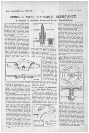
A New Feature in Disc Clutches.
THE invention of John Weller, No. , 273,428, relates to plate clutches, and its main object is to provide a means for pressing the discs together, which gives considerable latitude for misalignment and also provides for a large number of points of pressure on the clamping plate. The levers which transmit pressure from the spring which surrounds the shaft to the clamping disc are made in the form of a cross, the upper extremity of which is formed like a ball and is free to rock as well as acting as a lever. The horizontal extremities of the cross bear on the disc and so distribute the pressure evenly over six points instead of three points as with the common arrangement. The central disc, which is gripped between the two outer discs, is mounted on a flexible centre made of leather or similar substance.