


BRISTOL CHASSIS AND THEIR DEVELOPMENT.
Page 64
Page 65
Page 66
If you've noticed an error in this article please click here to report it so we can fix it.
Minor Improvements to the Existing Range. Three Robust Chassis Designed For Hard Work and Low Maintenance Costs.
WHEN a concern decides to continue its existing range of models for another season, with minor alterations only to details, it is clear that the manufacturing part as well as the designing section of the works are well satisfied that the vehicles are up to date
and capable of little possible all-round improvement, even though an entirely new layout be planned. This is the case with the Bristol Tramways and Carriage Co., Ltd. During the past few years a large number of vehicles produced by this company have been in regular service in all parts of the country and have given satisfactory results all round.
Naturally, certain modifications in details have been found advisable, but, as the dictates of service have been recorded, so the modifications hat, e been included, with the result that the chassis as turned out at present represents a very satisfactory state of affairs for all concerned. When a new model is introduced and an existing one scrapped, maintenance work is apt to become a little awkward, owing to the spare-part bogey, whereas with a current model this defect is largely avoided.
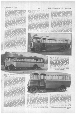
Broadly speaking, three chassis are being manufactured : a 3 to 4-ton lorry type, a 2-ton or 20-seater coach or bus chassis, and a light passenger-type 32seater bus or 26-seatcr coach chassis. These vehicles have already been de•. scribed in The Commercial Motor, so that readers will be familiar with them. However, information concerning the modifications for 192S is here followed by a brief specification of each type.
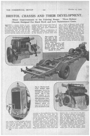
Dealing first with the B-type chassis, which is intended to be used as a light low-load passenger vehicle and is available with a variety of bodies, the chief
features are: a low level to the platform, adenhate seating accommodation and a layout in which maintenance work is rendered as easy as possible. When the chassis was described in the issue of The Commercial Motor for October 12th, 19264 a transmission brake was included in the layout; the new chasSis, however, has what might be termed a six-drum braking system.
Actually the pedal applies shoes within each of the four drums, whilst
the hand lever applies separate shoes in the rear drums only. The shoes are now die-castings and are fitted with a very ingenious farm of adjustment, the subject of a detail drawing. The shoes, of course, lie side by side. Each pair is joined by two screwed brass sleeves, on the oufside of which a worm Is cut. Meshing with this svorm—which, incidentally, forms the worm-wheel part—. is a further worm operated by a key. The key, by the way, can be inserted into the drums without dismantling any part whatever. In this way a micrometer adjustment for each shoe is obtained.
• The engine for this chassis now has a full-pressure lubrication system throughout. The old gear-type pump has not been altered, but passages have been cast in the sump and crankcase to lead oil direct to the three camshaft bearings and the three Main bearings of the crankshaft, the big-ends of the connecting rods obtaining• their supply of lubricant via internally-drilled passages in the crankshaft itself. It will be recalled that the pump is submerged in the sump, the rear end of which is covered by a large fairly coarse-mesh gauze. No relief valve is fitted to the system, but the normal pressure of .15 lb. per sq. in. is largely controlled by a series of holes in a tube protruding from the end of the longitudinal gallery running along the crankcase, which also serves the pur pose of lubricating the distribution chain.
There is another alteration which. although not important in itself, nevertheless assists materially in ease of maintenance. It will be recalled that the dynamo is driven from a shaft enclosed within a tubular extension attached to the rear cheek of the timing cover. This shaft has been lengthened considerably! in •order that the dynamo can clear the gear quadrant with the forward type of steering. The instrument is vertically disposed and is driven through a pair of spiral spur gears. All bearings in the drive are fed with oil under pressure from the main system, the excess lubricant draining back to the sump again through suitable channels. In passing, it might be mentioned that the whole assembly for the dynamo drive is slidably mounted on the rear cheek of the timing case and also on the upper face of a bracket protruding from the crankcase. The shaft is located in a flanged cover which engages with an oval spigot in the timing case and so prevents upand-down movement, but the shaft line, together with the chain pinion, can be moved outwards to take up slackness in the distribution chain.
Difficulty is often experienced in the winter with buses that have to stand some little time between their various runs, the engines becoming cold and taking a long time to warm up. To avoid this difficulty, the Bristol Tramways and Carriage Co. have fitted a new type of radiator which is equipped with shutters that protect the radiator from draughts and conserve the heat. The shell itself is an aluminium casting (which is easily detachable by undoing four nuts), and the shutters are located in fibre bearings so that lubrication is unnecessary. The shutters themselves can be operated by a lever in the driver's cab. The whole unit is
mounted on rubber buffers instead of the springs formerly employed.
To facilitate repair work, the clutch shaft has a special type of universal joint at its rear end. Actually, a double type of spider is used, in conjunction with an ordinary fabric flexible joint, but it is mounted in such a way that the locating ball and bush in the driving and driven elements are selfcontained within the auxiliary spider plates. In this way the locating pieces and the fabric joint can be dropped out of position immediately after removing the spider bolts and without dismantling any other parts. Apart from a new spare wheel carrier, the vehicles remain very much as throughout the present year.
The wheelbase is 5 ft. 7 ins., the track at the front is 6 ft. in, and at the rear 5 ft. 8 ins., whag the height of the frame is 25 ins, from the ground. With this layout a turning .circle of 58i ft. is permissible. The weight unladen! is 2 tons 16 cwt., the overalllength 24 ft 9 ins., and the overall width 7 ft.
The engine, known as the G.W.. type, has foil' cylinders with a 44-in. bore and 51.in. stroke, and gives a power output of 52 b.h.p. at 1,000 r.P.m. and
75 b.h.p. at 2,000 r.p.m.; the R.A.C. rating is 32.4 h.p. The four cylinders are cast monobloc and are fitted with a detachable head. The crankshaft, as already indicated, is mounted on three main bearings, the connecting rods of the latest type being machined from Duralumin stampings. Aluminium pistons are used and have three rings, the lowest one of which acts as a scraper.
These features have brought the enB39
right up to date and enabled high revolution speeds to be Maintained without the power dropping off materially and without undue vibration. The camshaft, of course, is contained within the crankcase and, as already stated, is driven by silent chain from a pinion on the end of the crankshaft. As an aid to good carburation the carburetter is at:leached to the forward end of a passage cast alongside the valve ports, suitable branches being arranged in the casting communicating with the inlet ports only. In this way the mixture is warmed up before it actually enters the cylinders.
A dry-plate asbestos-lined cluteh with a self-locking adjustment conveys the the se through a four-speed and reverse gearbox (separately mounted and offset
in the chassis), thence through a tubular propeller shaft to an underslune rear axle. The tyre equipment is really adoquate and up to the work of carrying a 32-passenger body, 34-in. by 7-in, single tyres being fitted to the front wheels and twin tyres of the same size to the rear wheels.
The springing of this chassis is quite noteworthy, as, by an arrangement in which the master leaves roll on cams, the effective length of the spring is reduced as the load is increased, with the result that the spring Is stiffened and the frequency autoniatically increased. No lubrication is required and, indeed, the working surfaces of the cams are faced with Ferodo fabric.
The 30 h.p. Two-ton Chassis.
The engine of the 2-ton chassis is a four-cylinder monobloe with a bore of 4 ins, and a piston-stroke of 5 ins., which has an R.A.C. rating of 25.6 h.p. At 1,000 r.p.m. 32 b.h.p. is developed, whilst at 1,850 r.p.m. 48 b.h.p. is delivered at the flywheel. Side-by-side valves are used in conjunction with a detachable cylinder head. There are many items concerning the power unit which have obviously received • careful attention in order to keep maintenance costs as low as possible. As an example, it may he noted that the valve guides are pressed into the cylinder block and are, therefore, renewable as occasion demands. Ample water spaces• are provided in the cylinder black and in the connecting pipes to the top and bottom of the radiator. The unit is three-point suspended in the frame from an aluminium crankcase. The crankshaft is held in three main bearings of ample proportions and is fed by splash from a gear-type pump submerged in the sump. The connecting rods and pistons are very similar, both in material and general shape, to those of the engine already described, but the carburetter is rather differently arranged. The instrument itself is a ClaudeI-Hobson and is attached to a vertical pipe which merges into a twobranch pipe to feed the cylinders. There
is an arrangement, however, whereby a portion of the exhaust gases can be bypassed to a heating chamber around the vertical pipe, which therefore assists materially in obtaining economical and even running of the engine in cold weather.
The clutch has a Ferodo-lined dry plate and the gearbox has four speeds. All the splined shafts are no less than 2 ins, in diameter and are hardened and ground, the gears themselves being casehardened, with the teeth ground to ensure quietness. The brake arrangement is arranged differently from that of the light low-load chassis. The foot-brake is of the contracting type, Ferodo and operates on a drum at the rear of the gearbox ; the hand-levee, however, operates internal-expanding shoes in the rear drums, which, incidentally, are 18 ins, ire diameter and 4 ins. wide.
The overhead-worm-driven rear axle is offered with a choice of three alternative gear reductions, 6, 7 . and 8 to 1 being the standardized ratios. The. weight of this chassis is approximately 2 tons. Two lengths of wheelbase are available-11 ft. and 12 ft. 6 ins.— and the respective lengths of chassis for these two wheelbases (from behind the dash) are 16 ft. and 17 ft. 6 ins. There is an option of solid or pneumatic tyres, the former embracing twin rears of 865 mm. by 120 mm. for 720 fitting ; the pneumatic tyres are 34-in. by 7-in. sti ai ght-sided cord.
Although the 4-ton chassis is very much more robust and generally larger than the 2-tonner, the specification is very similar. The cylinders are east in pairs instead of being monobloe, and have a bore of 4 ins, and a pistonstroke of 51 ins, respectively, the general disposition of the components being largely the same as on the 30 h.p. 2-ton chassis. Sixty b.h.p. at 1,800 r.p.m. is developed. There is a governor totally enclosed in the crank-chamber which limits the engine speed to 2,000 r.p.m.
A Renolds silent chain is used for driving the camshaft and magneto shafts, whilst the carburetter—a Clandel-Hobson—is fitted with a starting choke and heat regulator, both operated from the driver's seat. The fuel tank has a capacity for 35 gallons and is slung under the rear of the chassis frame. On this chassis, also, there is a choice of three axle ratios, these being 6-i to 1, 7.2-3 to 1, and 8.1-3 to 1. Again a choice of •tyres is offered, singles being fitted to the front wheels and twins to the rear in each case. The pneumatic tyres are 38-in, by 7-in. straight-sided cords.
With alternative wheelbases of 15 ft. 4 ins. an a 16 ft. respectively, the lengthsfrom the dashboard to the end of the frame are 18 ft. 6 ins. and 20 ft., whilst the overall dimension is 22 ft. 9 ins. in the one case and 24 ft. 3 ins, in the other.