


SIX-WHEELER DRIVING ON ALL WHEELS.
Page 62
Page 63
If you've noticed an error in this article please click here to report it so we can fix it.
Brief Details of a new F.W.D. Model which Embodies Particularly Interesting Features.
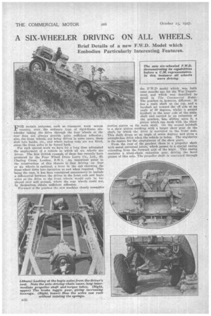
FOR certain purposes, such as transport work across country, even the ordinary type of rigid-frame six-. wheeler taking the drive through the four wheels at the rear does not always provide quite sufficient adhesion ; also, the front wheels; not being driven in some eases, these stub into banks, etc., and where radius rods are not fitted, cause the front axles to be forced back.
For such special work we have for a long time advocated the employment of a vehicle in which all six wheels are' ariven. The first British example of these has recently been produced by the Four Wheel Drive Lorry Co., Ltd., 46, Charing Cross, London, S.W.1. An important point in the construction of this chassis is that driving ' on four, or six wheels is optional, a lever in the cab throwing the front-wheel drive into operation as and when required. This 'being the case, it has been considered unnecessary to include a differential between the drives to the front axle and bogie axles as the drive to the front wheels would only be tunployed over, soft ground, where the rear wheels could not, by themselves, obtain sufficient adhesion.
Forward of the gearbox the new machine closely resembles
the F.W.D model which was built some months ago for the War Department, and which was described indetail in The Commercial Motor. The gearbox is, however, different. It has a main shaft at the top, and a layshaft set toward the off side at an angle of 30 degrees, whilst a second layshaft at the near side of the main shaft and carried in an extension of the gearbox' has, sliding upon it, a pinion which can mesh with the third motion pinion on the main shaft. On the second layshaft is a skew -pinion meshing with' a larger skew gear on the shaft, by which the drive is conveyed to the front axle. This shaft drops at an angle of seven degrees and gives a straight-line drive when the vehicle is laden. The angularity is the reason for the employment of the skew gears.
From the rear of the gearbox there is a propeller shaft with metal universal joints, which passes to a special casing extending from the forward axle of the bogie. This casing contains a silent-chain reduction gear, driving the bevel pinion of this axle. The propeller shaft is continued through
this casing to another cardan shaft, which conveys-the drive to a second casing of similar construction, also containing a chain reduction gear, in this instance driving the bevel pinion of the second axle of the bogie. There is no differential between the two axles of the bogie.
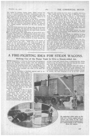
r. The suspension of the bogie is on the W.D. principle. although the spherical spring seatings on the present model will shortly be replaced by others of trunnion pattern. At each side, two inverted semi-elliptic springs are mounted on a rocking member fulcrumed on the line joining the two axles.
The foot brake operates on all wheels when the front-wheel drive is in operation, and upon the four wheels at the rear when only four wheels are driving; the hand brake controls shoes on the rear wheels only. tf ?It is claimed that the employment of front-wheel drive increases the coefficient of adhesion from 65 per cent, of the weight to 100 per cent.; in addition, a front-wheel-driven vehicle answers much more readily to the steering, without drifting sideways or causing material to bank against the front wheels.
A feature -of the driving arrangement is the length of the shaft between the axles. With axles 4 ft. apart' the centres of the universal joints are approximately 2 ft. apart, but, in this particular machine, the bevel-drive is so arranged that the pinions are at opposed sides of the axles, one pinion being in front of the leading axle of the bogie and the other behind that at the rear, so that the length between the universal joints is increased to 4 ft. 7 ins. where the axle centres are 4 ft. apart—a striking alteration.
This means that in the first case a difference in level of 9 ins, between the axles results in a universal-joint angle of 20 degrees 30 mins., whereas in the F.W.D. machine a difference of 13 ins, in the level gives a joint angle of only 13 degrees 18 mine. on the 4-ft. 7-in. shaft. To obtain such a movement in the case of the short shaft would entail an angle of 28 decrees 30 mine. The result is that the universal joint wear is reduced and the efOcieney is increased. Another advantage is that a greater difference can be allowed in the levels of the axles, and there is less likelihood of one axle or wheel being suspended in mid air when traversing rough ground.
Tubular torque rods with ball joints connect the bogie axles to a channel cross-member fitted between the castings which carry the spring fulcrums.
The braking on the rear wheels, In addition to being compensated, affords an increasing leverage as the lever is moved ; this enables the slack to be taken up quickly and increasingly powerful braking to be effected.
The-six-wheeler is being made in three models: the DL., which we illustrate ; the D.H., in which the driver is seated above the engine, as in the ordinary F.W.D. vehicle ; and the D.B., in which the driver sits behind the engine. In the D.H. and D.B. types the engine may be coupled direct to the gearbox without a reducing gear, if required. When the reducing 'box is wanted, either of two types may be employed to give ratios of 1 to 1 and 1 to 0.725 or 1 to 1 and 1 to 2.23.