


A NEW LIGHT SIX-CYLD
Page 58
Page 59
Page 60
Page 61
If you've noticed an error in this article please click here to report it so we can fix it.
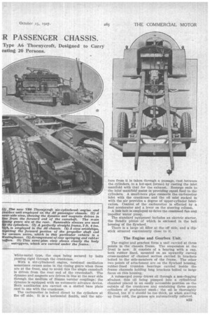
:R PASSENGER CHASSIS.
MHERE has been a decided call recently, and par
ticularly from municipal users of passenger chassis, for vehicles which will .enable faster services to be inaugurated. To permit this speeding up it is essential to provide much improved acceleration without undue recourse to the gearbox, and the chassis with the sixeyfinderedpower unit is the one which best answers this call.
Naturally, the braking power must be ample; consequently, braking on all wheels is almost essential, and to assist in reducing the fatigue of the driver these brakes should, preferably, be operated through a servo mechanism.
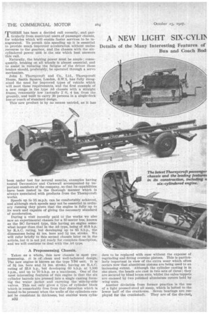
John I. Thornycroft and Co., Ltd., Thornycroft House, Smith Square, London, -S.WA, has fully recognized the need for improved types of vehicle which will meet these requirements, and the first example' of a new . range is the type AG chassis with " a straight frame, reasonably low (actually 2. ft. 4 ins. from the ground), and built to carry 20 persons in a single-deck
bus or coach of standard design. • This new product is by no means untried, as it has been under test for several months, examples having toured Devonshire and Cornwall accompanied by important. members of the company, so. that its capabilities have been tested in the thorough manner which is always associated with products from the Thornycroft works.
Speeds up to 55 m.p.h. can be comfortably achieved, and although such speeds may not be essential in ordinary running they prove that the engine is fully up to its work and capable of giving the necessary standard of acceleration.
During a visit recently paid to. the works we also saw-an experimental chassis for a 32-seater bus, known as the BC forward type, this having an engine somewhat larger than that in the A6 type, being of 40.8 h.p. by R.A.C. rating, but developing up to 85 b.h.p., the dimensions being 41 ins, bore and 51 ins. stroke. We will refer briefly to this second chassis later on in the article, but it is not yet ready for complete description, and we will continue to deal with the A.6 type.
A Prepossessing Chassis.
Taken as a whole, this new chassis is most prepossessing. it is of clean and well-balanced design. The new engine is known as the type Yri6 unit. It is of 31 ins, bore and 51 ins, stroke, having an R.A.C. rating of 33.8 h.p., but developing 60 b.h.p. at 1,500 r.p.m., and up to 70 b.h.p. as a maximum. One of the most interesting features of this engine is that the six cylinder barrels are pressed into a single casting forming the water jacket and carrying the side-by-side valves. This not only gives a type of cylinder block which is remarkably free from that distortion which is bound to be present when the walls of the cylinders cannot be consistent in thickness, but enables worn cylin B32
ders to be replaced with ease without the expense of regrinding and fitting oversize pistons. This is particularly important in view of the extra wear which often occurs now that aluminium pistons are being used to an increasing extent. Although the cylinder casting is in one piece, the heads are cast in two sets of three ; they are secured by blind brass nuts, 'whilst the valve tappets are encased by two polished aluminium covers held by wing nuts.
Another devia tien from former practice is the use of a light pressed-steel oil sump, which is bolted to the lower half of the crankcase. Seven bearings are employed for the crankshaft. They are of the die-cast,
white-metal type, the caps being secured by bolts passing right through the crankcase.
With a six-cylindered engine, torsional oscillation sometimes causes noise in the timing gears when these are at the front, and to avoid this the single camshaft is driven from the rear end of the crankshaft. The dynamo and magneto are driven in line at the near side through the medium of Simms vernier couplings; the dynamo is equipped with an automatic advance device. Both auxiliaries are carried on a• slotted base plate cast in one with the crankcase.
The carburetter. is bolted direct to the cylinders at the off side. It is a horizontal Zenith, and the mix
ture from it is taken through a passage, cast between the cylinders, to a hot-spot formed by casting the inlet manifold with that for the exhaust. Resurge ends to the inlet manifold assist in providing equal feed to the cylinders. A small-bore pipe connects the carburetter inlet with the crankcase and the oil mist slicked in with the air provides a degree of upper-cylinder lubrication. Control of the carburetter is effected by a foot accelerator and a lever on the steering column.
A link belt is employed to drive the combined fan and impeller water pump.
The standard equipment includes an electric starter, the Bendix pinion of which is enclosed in the bell housing of the flywheel.
There is a large oil filler at the off side, and a dipstick situated conveniently close to it.
The Engine and Gearbox Unit.
The engine and gearbox form a unit carried at three points in the chassis frame. The suspension at the -front is new. It consists of a bearing with a cap, both rubber lined, mounted on an upwardly curved cross-member of channel section carried in brackets bolted to the side-members of the frame. The other two points of attachment are on the flywheel housing, • rubber-lined trunnion bearings carried inside the frame channels .holding long brackets bolted to large faces on this housing.
A submerged pump draws oil through a non-clogging _sfrainer, this oil being pumped into a cylindrical chamber placed in an easily accessible position on the outside of the crankcase and containing three gauze cylinders of graduated mesh; the oil is thoroughly filtered, but if it should be too thick, as when starting up from cold, the gauzes are automatically relieved. B33 After being filtered the oil passes through ducts in the crankcase to the camshaft bearings and the main bearings. whilst the big-ends are lubricated through
the drilled crankshaft. Lubrication of the timing wheels is effected by the overflow from the relief valve. Before returning to the pump the oil has to pass through a perforated metal diaphragm extending over the whole area of the base chamber. Only one external pipe is used in the whole system, this being the pipe to the pressure gauge.
A Thermostat Water Regulator.
As regards the engine cooling, there is a thermostat water regulator mounted in the top-water connection.
The 'radiator itself is entirely new. It is or the gilled-tube type with header and bottom tank. The bottom tank is cast with a hole through it to take the starting-handle shaft.
To avoid any misconception, we would here point out that although the camshaft is driven from the rear the dynamo and magneto take their drive from a gearwheel at its front end.
A small point, but one which shows that the designers have easy maintenance in view, is that lugs to assist in levering up the cylinder heads are provided upon them.
Transmission Details.
Four forward speeds are afforded by the gearbox, the ratios being: first, 5.28 to 1; second, 2.62 to 1; third, 1.58 to 1; fourth, 1 to 1; reverse, 8.25 to 1, and the corresponding vehicle speeds at 1,500 r.p.m. of the engine are: first speed, 5* m.p.h.' second speed, 11 m.p.h.; third speed, 184 m.p.h.; fourth speed, 28i m.p.h. (with 34-in. by -7-in, pneumatic tyres and 54 to 1 axle ratio). The whole of the gear-change mechanism, including the selector rods, is carried on the top of the gearbox in aluminium castings. At the left of the gearbox is a long brake lever, whilst at the right, or off side, is a power take-off for the tyre pump, which is another standard fitting.
_Power is conveyed to the gearbox through a singleplate clutch with asbestos-fabric friction material. The driven member is light anti, with the use of a clutch stop, facilitates gear changing.
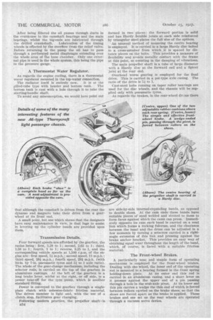
Following modern practice, the propeller shafts is B34 formed in two pieces; the forward portion is solid and has Hardy flexible joints at each side reinforced by triangular steel plates the full size of the spiders.
An unusual method of mounting the centre bearing is employed. It is carried in a large Hardy disc bolted to a cross-member from which it is spaced by distance pieces on the bolts. This provides a measure of flexibility and avoids metallic contact with the frame at this point, so assisting in the damping of vibrations.
The main propeller shaft is a tube of large diameter with a Hardy disc at the fOrward end and a Spicer joint at the rear end.
Overhead worm gearing is employed for the final drive. This is carried in a pot-type axle casing. The ratio of the drive is-51 to 1.
Cast-steel hubs running on taper roller hearings are used for the disc wheels, and the chassis will be supplied only with pneumatic tyres.
As regards the brakes, in the rear-wheel drtrus there are side-by-side internal-expanding bands, as opposed to double shoes. At the cam ends these bands have suitable pieces of steel welded and riveted to them to form faces against Which the cams can press. Immediately opposite its cam each band is Carried on a neat link which forms a rocking fulcrum, and the clearance between the band and the drum can be adjusted in a few moments by turning a setscrew carried in a rightangle extension of this link and pressing against the brake anchor bracket. This provides an easy way of obtaining equal wear throughout the length of the band, which, of course, is faced with a suitable friction material.
The Front-wheel Brakes.
A particularly neat and 'simple form of operating mechanism is employed for the front-wheel brakes. Dealing with one wheel, the inner end of the operating rod is mounted in a bearing formed in the front spring
holding-down plate. At its outer end this rod is carried in an aluminium casing, and a short lever on it presses against the upper end of a pin passing through a hole in the stub-axle piv.ot. At its lower end this pin carries a wedge the thin end of which is forced between rollers carried on the brake shoes, so that the shoes are forced apart as the brake is applied. These brakes and one set on the rear wheels are operated through a vacuum servo device.
Much attention has been given to the suspension. The springs are overMung and are secured by axle bolts set at an angle, thus giving a short bearing on the main spring leaf, so that the 'action of the spring is pot impaired and stretching of the bolts through undue stressing is avoided, whilst the bolt heads lock against each other and cannot turn. Above each rear spring are two round rubber buffers carried in brackets bolted to the drum and provided with slotted holes for adjustment. The second leaf of each spring is carried round the spring eyes, ana the pins are held by cotter bolts so that they can easily be removed.
The frame Is perfectly straight. Its side-members have a depth of 5i ins, and the flanges are 4 ins. wide. All the cross-members are of pressed steel, and the one in front of the rear axle is shaped around the propeller shaft.
.Conforming with modern practice, permanent outJiggers are bolted right across the underneath of the frame. These are of U-section pressed steel.
The petrol tank is of D shape, inverted and mounted under the rear of the frame with a long spout projecting to the near side.
Very wide wings are fitted at the front. These are extended to form the bonnet plinths. Incidentally, the bonnet is tapered upwards and to the sides.
The dash itself is of wood and carries a steel instrument board ; the foot plates are in armoured three-ply.
• . Tecalemit lubrication is employed throughout the ch.assis.
A worm-and-wheel-type steering gear with taperroller thrust bearings at each end of the worm shaft is employed. The worm-wheel is complete, so that it can be changed round to several new positions as wear occurs, the lever being carried on a splined shaft. The main particulars and dimensions of the chassis are as follow: Weight, 421 cwt.; wheelbase, 15 ft.; height of frame loaded, 2 ft. 4 ins.; turning circle, 60 ft.; track (front) 4 ft. 111 ins., (rear) 5 ft. 01 ins.; ground clearance, minimum 10 ins, to the rear axle. The tyres are 34-in. by 7-in, pneumatics all round, or 32-in. by 6-in, single front and twin rear can be fitted at an extra charge. The price of the chassis with full equipment is £725.
The equipment includes a 12-volt lighting set, with five lamps and an electric Irorn, a tyre carrier with spare wheel and tyre, combined speedometer and mileage recorder, mechanical tyre pump bolted to the )gearbox casing, electric starter and a complete set of tools. A well-finished fender for the radiator can be supplied at an extra cost.
Now as regards the BC forward chassis, this has a drop frame giving a very low-loading level, and its -powerful engine provides rapid acceleration, a high average speed and good hill-climbing.
The four-wheel brakes are operated by vacuum servo as in the chassis just described. There is a transmission brake at the end of the forward portion of the propeller• shaft, the spokes of the drum being curved and giving a large area for air cooling. Two contracting shoes are employed on this brake.
The forward propeller shaft joint is of the Hardy type, the other two are of the all-metal Spicer pattern, and here again the centre bearing is supported in a Hardy joint mounted behind the transmission brake.
Frame kick-ups are employed over the inverted pot axle, which has underneath worm-drive and underslung springs. As a matter of fact, this chassis, aft of the gearbox, is almost a replica of the T_TB forwardcontrol model. _