


THE FREE-WHEEL IN THE TRANSMISSION LINE.
Page 56
Page 57
If you've noticed an error in this article please click here to report it so we can fix it.
The A.C. (Acedes) System which Employs a Free-wheel Clutch in the Plate Member of the Main Clutch.
FOLLOWING up our desire to describe the various systems of free-wheel now before the public, we this week deal with the plan adopted in the case of the A.C. ears, having in our issue of October 4th described the Joseph system, and in that of October 11th the Humfrey-Sandberg gear. In both the systems with which we have already dealt, the free-wheel mechanism is situated behind the gearbox and between it and the propeller shaft, the object being to free the gear shafts from any drive from the rear wheels during the operation of gqar changing, as well as to provide a free-wheel.
In thq present instance the free-wheel is situated within die single plate of the ordinary clutch, the objects aimed at being to assist in changing gear by re
lieving the gear shaft of the spining effect of the clutch plate, and by so doing to render it more easily adapted to a change of rotary velocity. The free-wheel also allows the propeller shaft and gears to overrun the engine when running down hill, and permits the use of second gear when in slow-moving traffic, where only intermittent engine power is required, as, when not tinder power, the car glides along without a sound.
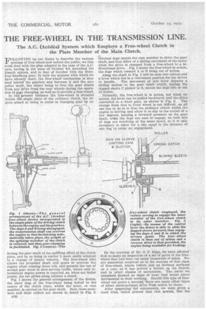
Fig. 1 shows the general arrangement of the device, the outer ring of the free-wheel being bolted to the centre of the clutch plate, whilst the inner, or cam member, is carried on the gear shaft. Both these members and their rollers are shown in detail in Fig. 2.
530 Internal dogs enable the cam member to drive the gear shaft, and they allow of a sliding movement of the latter when the drive is changed from a free-wheel to a bidirectional drive. Fig. 1 shows the free-wheel in action, the dogs which connect A to 13 being out of action.
Along the shaft in Fig. 1 will be seen two collars and a lever which lies in a convenient position for the driver to handle. The movement of this lever imparts a sliding motion to the gear shaft which, having the dogged sleeve C pinned to it, moves the dogs into or out of action.
Normally, the free wheel IA in action, but when required, the lever can be pulled backward, and the drive converted to a fixed gear, as shown in Fig. 3. The change from free to fixed wheel is not difficult, as all one has to do is to free the ordinary clutch whilst the engine is driving and allow it to slip to the extent of a few degrees, keeping a forward pressure on the gear shaft, whtn the dogs are sure to engage, as both sets of dogs are revolving at the same speed, so it is only necessary to allow for a slip equal to the distance of one dog to cause an engagement.
By the courtesy of Mr. S. F. Edge, we were allowed first to make an inspection of a set of parts of the freewheel that had been run many thousands of miles. We are somewhat sceptical as to the success of this class of free-wheel, where rollers jam on inclined surfaces on a cam, as it has proved a failure on the bicycle and in other classes of mechanism. The parts we examined showed no signs of wear that would prove detrimental to their working. Should this type of freewheel not prove a success, there are many other types of silent unidirectional drive from which to—chose.
After inspecting the components, we were given a road trial, which proved that this system, like the
others we have tried, will give a fresh interest to pleasure riding, which, of , course, includes char-h-bancs riding. As our object in investigating this subject is to ascertain the merits or demerits of the free-wheel as applied to commercial vehicles, the car on which we made the trial did not give us much information, as, being a light vehicle, gear changing in ordinary circumstances would ..not be a very difficult matter and, although any change either up or down can be made without the slightest difficulty, it left us wandering how this ',articular plan (with the free-wheel in front of
the gearbox would act if applied to a heavier vehicle. For the lighter types of ear the system is certainly
a good one, as it is Tittle being asked of the free-Wheel, for it only transmits engine torque (which probably accounts for the little _signs of wear) and it acids but little to the cost or weight. For a heavy vehicle, however, we are still of the opinion that-the free-wheel should be situated behind and not in front of the gearbox, and that it should be possible to engage an idling or a still engine whilst running down hill, 'whenever desired.