


THE FIRST PETROL-ELECTRIC SIX-WHEELER.
Page 53
Page 54
If you've noticed an error in this article please click here to report it so we can fix it.
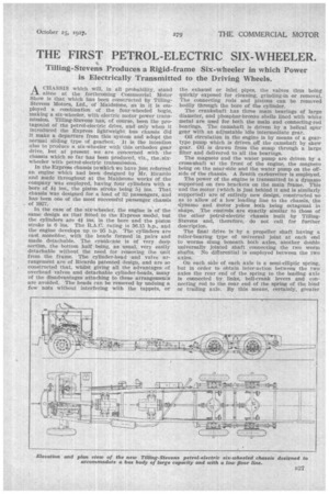
Tilling-Stevens Produces a Rigid-frame Six-wheeler in which Power is Electrically Transmitted to the Driving Wheels.
IXCHASSIS which will, in all probability, stand . alone at the forthcoming Commercial Motor Show is that which has been constructed by TillingStevens Motors, Ltd., of Maidstone, as in it is employed a combination of the four-wheeled bogie, making a six-wheeler, with electric motor power transmission. Tilling-Stevens has, of course, been the protagonist of the petrol-electric drive, and only when it introduced the Express lightweight bus chassis did it make a departure from this system and adopt the normal sliding type of gearbox. It is the intention also to produce a six-wheeler with this orthodox gear drive, but at present we are concerned with the chassis which so far has been produced, viz., the,sixwheeler with petrol-electric transmission.
In the Express chassis to which we have Just referred an engine which had been designed by Mr. Ricardo and Made throughout at the Maidstone works of the company was employed, having four cylinders with a bore of 41 ins., the piston stroke being 5i ins. That chassis was designed for a load of 32 passengers, and has been one of the most successful passenger chassis of 1927.
In the case of the six-wheeler, the engine is of the same design as that fitted to the Express model, but the cylinders are 4iins. in the bore and the piston stroke is 6 ins. The R.A.C. rating is 36.15 b.p., and the engine develops up to 95 h.p. The cylinders are cast monobloc, with the heads formed in pairs and made detachable. The crankcase is of very deep section, the bottom half being, as usual, very eaSily detachable without the need for removing the unit from the frame. The cylinder-head and valve arrangement are of Ricardo patented design, and are so constructed that, whilst giving all the advantages of overhead valves and detachable cylinder-beads, many of the disadvantages attaching to these arrangements are avoided. The heads can be removed by undoing a few nuts without interfering with the tappets, or the exhaust or inlet pipes, the valves thus being quickly exposed for cleaning, grinding-in or removal. The connecting rods and pistons can be removed bodily through the bore of the cylinder.
The crankshaft has three main bearings of large diameter, and phosphor-bronke shells lined with white metal are used for both the main and connecting-rod bearings. The camshaft is driven by a helical spur gear with an adjustable idle intermediate gear.
Oil circulation in the engine is by means of a geartype pump which is driven off the camshaft by skew gear. Oil is drawn from the sump through a large filter and delivered to all the bearings.
The magneto and the water pump are driven by a cross-shaft at the front of the engine, the magneto being on the near-side and the water pump on the offside of the chassis. A Zenith carburetter is employed.
The power of the engine is transmitted to a dynamo supported on two brackets on the main frame. This and the motor (which is just behind it and is similarly supported) are of entirely new design, constructed so as to allow of a low loading line to the chassis, the dynamo and motor yokes both being octagonal in shape. The controls are exactly similar to those of the other petrol-electric chassis built by TillingStevens and, therefore, do not call. for further description.
The final drive is by a propeller shaft having a roller-bearing type of universal joint at each end to worms slung beneath both axles, another double universally jointed shaft connecting the two worm shafts. No differential is employed between the two axles.
On each side of each axle is a semi-elliptic spring, but in order to obtain Inter-action between the two axles the rear end of the spring to the leading axle is connected by links, bell-crank levers and connecting rod to the rear end of the spring of the bind or trailing axle. By this means, certainly, greater total spring length is obtained at the expense of merely a few moving joints, viz., eight on each side, or 16 in all.
The wheels are pressed steel discs and the wheel hubs are fitted with tapered roller bearings. The tyre equipment is 36-in. by 8-in. straight-sided pneumatics, singles on all wheels.
The whole of the weight is carried by the back
axle casing, only the drive being taken by the axle shafts. These shafts are of nickel-chrome steel, and by withdrawing them and disconnecting the universal joints the whole of the differential can be removed without disturbing the road wheels.
The total weight of the chassis is 4 tons 10 cwt., and it is designed to carry a total load of 7 tons, including the body.