


Patents Completed.
Page 20
If you've noticed an error in this article please click here to report it so we can fix it.
Complete specifications of the following patents will be sent to any address in the United Kingdom upon receipt of eightpence per copy at the Sale Branch, Patent Office, Holborn, W.C.
WORM GEAR. — Dawson. — No. 21,556, dated 12th October. 1908.—This invention relates to worm gearing of the type in which the worm is divided transversely, one portion being adjustable relatively to the other for the purpose of taking up any backlash. This relative adjustment of the two parts of the worm is effected by means of a rotary member which is mounted on the worm-spindle so as to be capable of revolving without sliding thereon. This rotary member is provided with screw threads which engage with threads formed on the adjust
able portion of the worm, so that, on the rotary member being rotated, the necessary adjustment can be effected.
DEVICE FOR RAISING THE WHEELS OF VEHICLES.—Hall.—No. 25,327, dated 25th November, 1908.—This invention relates to a device for raising or jacking the wheels of vehicles. It consists of a cast shoe, the tread of which is semi-circular, and has a flat. surface upon which the shoe rests when the wheel is raised from the ground. The shoe is also formed with a leg or supporting member, which is adapted to engage a bracket that is bolted to the feline of the wheel. When it is required to raise the wheel the shoe is fixed in the bracket and the wheel rotated, so that it will ride up on to the shoe.
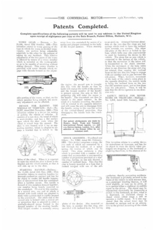
STARTING HANDLE..—Dallisou.No. 11,162, dated 11th May, 1909.—This invention relates to starting handles for internal-combustion engines and has lotits object to render the handle inoperative or disconnected from the crankshaft when a. backfire occurs. The handle is formed of two members hinged together, cne member being loosely mounted on the crankshaft. Pivoted to this member, is a second arm, one end of which is formed with teeth which are adapted to mesh with a pinion that is rigidly secured to the crankshaft. The other end of the second arm is formed with 4 conical pin or projection that is adapted to enter a similarly-shaped recess formed in the hinged member of the atarting handle. This hinged member is normally swung
away frond the crankshaft bv means of a spring and plunger contained) in the body of the hinged member. When starting the engine, the second arm is brought into line with the handle so that its teeth will engage the teeth of the pinions, and the hinged member of the handle is pressed against this arm so that its projecting pin will enter the recess ill the handle. The crankshaft can then be turned in the usual manner. In the event of a backfire occurring, the pinion will be rotated in the opposite direction and will cause the arm to disengage from the handle, owing to the cam-like action of the conical-shaped projection, thus disengaging the handle from the crankshaft.
SHOCK A BSOR.BE R.— Wondh ead and Others.-No. 2,962, dated 8th February, 1909.--This device comprises a strap, the two ends if which are connected by a bolt through the medium of a spiral spring, the tension of which eau be varied. This strap embraces a ring which is provided with a number of recesses that accommodate a corresponding number of projections provided on a disclike ring, having, on one side thereof, a number of inclined faces, This disc-like ring is loosely mounted on a boss that is formed integral with one of the side
plates of the device. Also mounted on the boss, is another disc-like ring, also provided with inclined faces, hut having
no prajectLns. Arranged between shoulders on the two disc-like rings are leaf springs which tend to force the inclined faces towards one another. The other side-plate of the device is bolted to the boss, which bolts may also conveniently he used for fastening the device to the vehicle. The strap has an arm which is connected to the springs of the vehicle, an that the movement of the latter will be transmitted to the shock absorber. When the movement, of the body takes place in one direction the strap and ring are rotated, thus causing the inclined faces on the two disc-like rings to engage with one another and to jam between the side-plates. When, however, movement of the body of the vehicle takes place in the opposite direction, the motion tends to bring the inclined faces on the two disc-like members apart, and so free them from the side-plates. Thus, it will be seen that the device operates in one direction only.
SAFETY DEVICE FOR MOTORBUSES OR TRAMCARS.—Mallings.— No. 1,019, dated 15th January, 1909.— This invention relates to a safety device for motorbuses or tramcars, and has for its object to warn the driver when passengers are stepping on the footboard or alighting therefrom, in the absence of the
donductor, thereby preventing accidents. The footboard is pivotally secured to the frame of the vehicle in such manner that, on a passenger treading thereon, it will yield slightly, or turn on its pivot, so as to operate either a visible or an audible signal to the driver. The signal may be transmitted electrically by connecting a switch to the footboard, so that, when it is depressed, an electrical circuit. is closed which either rings a bell or operates a visible signal. It is also suggested that the actual trea,1 may be mounted on springs and as an alternative to the pivotal mounting of the whole step.