


Torque-converter Progress
Page 68
If you've noticed an error in this article please click here to report it so we can fix it.
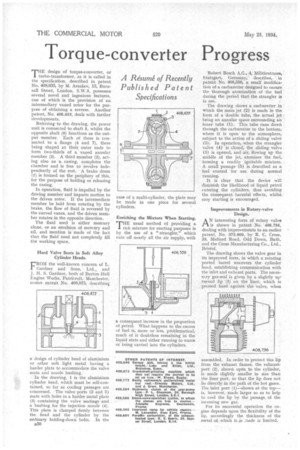
THE design of torque-converter, or turbo-transformer, as it is called in the specification, described in patent No.. 408,635, by M. Astafiev, 13, Burnsail Street, London, S.W.3, possesses several novel and ingenious features, one of which is the provision of an intermediary vaned rotor for the purpose of obtaining a reverse. Another patent, No. 408,653, deals with further developments.
Referring to the drawing, the power unit is connected to shaft 5, whilst the opposite shaft (6) functions as the output member. Each of these is connected to a flange (4 and 7), these being shaped at their outer ends to form two-thirds of a vaned annular member (3). A third member (2), acting also as a casing, completes the chamber and is free to revolve independently of the rest. A brake drum (1) is formed on the periphery of this, for the purpose of holding or releasing the casing.
In operation, fluid is impelled by the driving member and imparts motion to the driven rotor. If the intermediate member be held from rotating by the brake, the flow of fluid is reversed by the curved vanes, and the driven member rotates in the opposite direction.
The fluid used is either mercury alone, or an emulsion of mercury and oil, and mention is made of the fact that the fluid need not completely fill the working space.
Hard Valve Seats in Soft Alloy Cylinder Heads.
L-ROM the well-known concern of L. Gardner and Sons, Ltd., and J. S. Gardner, both of Barton Hall Engine Works, Patricroft, Manchester, comes patent No. 408,875, describing
a design of cylinder head of aluminium or other soft light metal having a harder plate to accommodate the valve . seats and nozzle bushing.
In the drawing, 1 is the aluminium cylinder head, which must be self-contained, so far as cooling passages are concerned. The valve ports (2 and 5.) mate with holes in a harder metal plate (3) containing the valve seatings and a bushing for the injection nozzle (4). This plate is clamped firmly between the head and the cylinder by the ordinary bolding-down bolts. In the
B50
Enriching the Mixture When Starting. rrHE usual method of providing a I rich mixture for starting purposes is by the use of a "strangler." which cuts off nearly all the air supply, with a consequent increase in the proportion of petrol. What happens to the excess of fuel is, more or less, problematical, much of it doubtless remaining in the liquid state and either running to waste or being carried into the cylinders. Robert Bosch A.G., 4, Militarstrasse, Stuttgart, Germany, describes, in patent No. 408,356, a small modification of a carburetter designed to ensure. the thorough atomization of the fuel during the period that the strangler is in use.
The drawing shows a carburetter in which the main jet (2) is made in the form of a double tube, the actual jet being an annular space surrounding an inner tube (1). This tube runs down through the carburetter to the bottom, where it is open to the atmosphere, subject to the action of a sliding valve (3). In operation, when the strangler valve (4) is closed, the sliding valve (3) is opened, and air, flowing up the middle of the jet, atomizes the fuel, forming a readily ignitable mixture. A small passage (5) is described as a fuel control for use during normal running.
It is clear that the device will diminish the likelihood of liquid petrol tntering the cylinders, thus avoiding the consequent harmful effects, whilst easy starting is encouraged.
Improvements in Rotary-valve Design,
AN interesting form of rotary valve is shown in patent No. 408,756, dealing with improvements to an earlier patent, No. 373,660, by R. C. Cross, 33, Midford Road, Odd Down, Bath, and the Cross Manufacturing Co., Ltd., Bristol.
The drawing shows the valve gear in its improved form, in which a rotating ported barrel uncovers the cylinder head, establishing communication with the inlet and exhaust ports. The necessary gas-seal is given by a slightly upturned lip (3) on the liner, which is pressed hard against the valve, when
assembled. In order to protect this lip from the exhaust flames, the exhaustport (2), shown open to the cylinder, is made slightly smaller in size than the liner port, so that the lip does not lie directly in the path of the hot gases. The inlet port (1)—shown at the top— is, however, made larger so as to help to cool the lip by the passage, of the incoming new gas.
For its successful operation the engine depends upon the flexibility of the lip, accordingly the thickness of the metal of which it is made is limited.