


A Simple and Efficient
Page 46
Page 47
If you've noticed an error in this article please click here to report it so we can fix it.
German Gas Producer
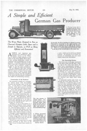
ASIMPLE and ingenious gas generator for commercial motor vehicles, known as the Wisco, and to which we made reference in our report of the recent Berlin Motor Show, is now giving satisfactory results in Germany, and is noticeable for its compactness. It employs charcoalas fuel, which costs only a fraction of the price of petrol, but is claimed, weight for weight, to give the same performance.
We are informed that users having experience of six months and over with the new plant, on heavy lorries doing constant service, have expressed much satisfaction and say that the cleanliness of the plant and the smooth working of the engine are outstanding features.
Construction of the Producer.
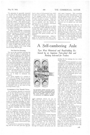
The generator consists of a rectangular firebox lined with fire-resisting material and having a grid at the bottom. At the front is a small: stoking aperture, which gives access to the fire above the grid and to the ash-pan below it. Above this aperture, which is normally closed by a plate, is a circular port, connected with a hand-driven blower by a short connecting pipe, in which a valve is incorporated to cut off the blower. The last-named delivers air into a space partitioned off from the firebox and opening on to the grid so that it flows through the grid again and through the charcoal fire.
Standing on top of the firebox is a long charcoal container, which communicates, through a hand-operated shutter, with the firebox below it. An air jacket surrounds both firebox and container, and the air from between the double walls, which is heated, is drawn in through a water compartment on the rear of the firebox. Thus water vapour is taken along with it so soon as the hand-driven blower is cut out and the plant begins to work on its own.
Within the water tank there is a pipe rising, vertically to the level of the water. It can be closed from outside by B28
a valve, which can be set in any desired position. Its function is to control the amount of combustion air and water vapour drawn into the firebox.
The Generating System.
The lower end of the pipe terminates in the space under the fire grid, whilst the top of the water box, above the water level, communicates through a pipewith the space between the double walls of the gas generator. Partitioned. off from the water box, between it and the firebox, is a space that communicates, at the top, through perforations, with the interior of the firebox, inside which a perforated baffle plate prevents the. charcoal and ashes from being. drawn in.
A horizontal suftion pipe leads out through the water space rearwards. It is crossed by a transverse pipe so that there are three openings available from which the generated gas can be drawn. Two of these, however, are plugged, only the most conveniently situated being employed, whilst in the latest model only the two transverse pipes are used. To prevent undue splashing of the water, baffle plates are fitted within the water. box,
The generator is generally mounted on the side of the vehicle opposite that on which the carburetter is situated, where the compact cleaning unit is car
ried. The two components are connected by a transverse pipe passing under the vehicle. The cleaner is provided with a vertical partition dividing it into two spaces—a large one, partially filled with water, and a small one, containing a mixture of two parts of oil with three of paraffin.
The gas enters through a horizontal tube which terminates in a horizontal chamber having an inverted U cross section. This communicates, through a perforated bottom plate, with the water, in which the downwardly extended sides of the chamber are submerged. They have comb-like serrations through which the gas passes into the water and thence to the space above it, which is filled with pieces of cork to prevent impure water from being drawn along with the gas.
The Final Gas Cleansing.
The top of the partition between the water and oil spaces is perforated to allow the gas to pass on to the oil chamber. This is subdivided by a plate extending downwards to below the oil level. Thus the gas is drawn through the oil. Above it there is a horizontal filter and above that again a large number of small coil springs, the function of which is to retain the last particle of hard matter the as may still be carry
ing with it. From the top of this chamber the gas flows on to the mixing valve. The small amount of oil that may be taken along with it is of advantage. as it helps to lubricate the cylinders.
The mixer consists of a tubular Tpiece with two flanges, the one serving for attachment to the inlet manifold and the other for fixing the carburetter, whilst another branch is connected with the gas supply and the side of the mixer is furnished with an air valve of the rotating-shutter type.. tray) a piece of oil-saturated rag which has first been ignited. Previously one of the plugged outlets of the suction pipe on the water box has to be opened to allow smoke to escape. Then the valve between the blower and the firebox is opened, and the former is operated for a few seconds, whereupon the engine can be started.
At first, unskilled drivers are liable to experience a little difficulty in apportioning the right amount of air, but with practice it should be possible to start the engine direct on gas. As an alternative the petrol system may be utilized.
Maintenance appears easy. Ashes require to be removed only once a day, whilst the cleaner has to be attended to
with equal frequency. This operation consists of merely introducing a hose and allowing water to run through the cleaner until it comes out pure. Once a week the charcoal container and firebox have to be cleaned. Half-burnt charcoal can be picked out and used again.
The cleaning unit has, likewise, to receive more thorough attention once a week, for the residue which has collected in the oil and water compart
ments has to be cleared out. Alter filtering through a cloth the old oil can be used again. This is all the work that is required, and as a saving in the fuel bill is said to be between 60 and 70 per cent., the extra trouble involved appears to be well worth while.