


Mounting for Rear Engines
Page 78
If you've noticed an error in this article please click here to report it so we can fix it.
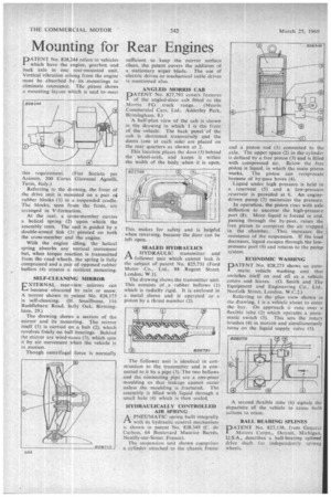
PATENT No. 828,244 refers to vehicles which have the engine, gearbox and back axle in one rear-mounted unit. Vertical vibration arising from the engine must be absorbed by its .mountings to eliminate resonance. The patent shows a mounting-layout which is said to-meet
this requirement. (Fiat Societa per Azionin, 200 Corso Giovanni Agnelli, Turin, Italy.) Referring to the drawing, the front of the drive unit is mounted on a pair of rubber blocks (1) in a suspended cradle. The blocks, seen from the front, are arranged in V-formation.
At the rear, a cross-member carries a helical spring (2) upon which the assembly rests. The unit is guided by a double-armed link (3) pivoted on both the cross-member and the engine.
With the engine idling, the helical spring absorbs any vertical movement but, when torque reaction is transmitted from the road wheels, the spring is fully compressed and a pair of opposed rubber buffers (4) creates a resilient mounting.
SELF-CLEANING MIRROR
EXTERNAL rear-view mirrors can become obscured by rain or snow. A mirror shown in patent No. 828,175 is self-cleaning. (H. Smallbone, 116 Raddlebarn Road, Selly Oak, Birmingham, 29.)
The drawing shows a section of the mirror and its mounting. The mirror itself (1) is carried on a hub (2), which revolves freely on ball bearings. Behind the mirror are wind-vanes (3), which spin it by air movement when the vehicle is in motion.
Though centrifugal force is normally sufficient to keep the 'mirror surface clean, the patent covers the addition of a stationary wiper blade. The use of electric drives or mechanical cable drives is mentioned also.
ANGLED MORRIS CAB
PATENT No. 827,793 covers features of the angled-door cab fitted to the Morris FG truck range, (Morris Commercial Cars; Ltd., Adderley Park, Birmingham. 8.)
A half-plan view of the cab is shown in the drawing in which 1 is the front of the vehicle. The back panel of the cab is shortened transversely and the doors (one at each side) are placed on the rear quarters as shown at 2.
This location places the door (3) behind the wheel-arch, and keeps it within the width of the body when it is open.
This makes for safety and is helpfu when reversing, because the door can be left open.
SEALED HYDRAULICS
AHYDRAULIC transmitter and follower unit which cannot leak is the subject of patent No. 825,731 (Ford Motor Co.. Ltd.. 88 Regent Street. London, W.1).
The drawing shows the transmitter unit. This consists of a rubber bellows (I) which is radially rigid. It is enclosed in a metal sleeve and is operated as a piston by a thrust member (2).
The follower unit is identical in construction to the transmitter and is connected to it by a pipe (3). The two bellows and the connecting pipe are a one-piece moulding so that leakage cannot occur unless the moulding is fractured. The assembly is filled with liquid through a small hole (4) which is then sealed.
HYDRAULICALLY CONTROLLED AIR SPRING
APNEUMATIC spring built integrally with its hydraulic control mechanism is shown in intent No. 828,349 (C. de Carbon, 64 Boulevard Maurice Barres, Neuilly-sur-Seine, France).
The suspension unit shown comprises a cylinder attached to the chassis frame and a piston rod (I) connected to the axle. The upper space (2) in the cylinder s defined by a free piston (3) and is filled with compressed air. Below the free piston is liquid, in which the main piston works. The piston can reciprocate because of by-pass bores (4).
Liquid under high pressure is held in a reservoir (5) and a low-pressure reservoir is provided at 6. An enginedriven pump (7) maintains the pressure.
In operation, the piston rises with axle deflection to uncover the high-pressure port (8). More liquid is forced in and, passing through the by-pass, raises the free piston to compress the air trapped in the chamber. This increases the resistance of the suspension. If the load decreases, liquid escapes through the lowpressure port (9) and returns to the pump system.
ECONOMIC WASHING
PATENT No. 828,273 shows an automatic vehicle washing unit that switches itself on and off as a vehicle enters and leaves. (O. Smith and The Equipment and Engineering Co., Ltd., Norfolk Street. London, W.C.2.)
Referring to the plan view shown in the drawing, I is a vehicle about to enter the bay. On approach it runs over a flexible tube (2) which operates a pneumatic switch (3). This sets the rotary brushes (4) in motion and simultaneously urns on the liquid supply valve (5).
A second flexible tube (6) signals the departure of the vehicle to cause both actions to cease.
BALL BEARING SPLINES
PATENT No. 827,138, from General Motors Corpn., Detroit, Michigan, U.S.A., describes a ball-bearing splined drive shaft for independently sprung wheels.