


The New Rover Motorcab.
Page 3
Page 4
If you've noticed an error in this article please click here to report it so we can fix it.
Details of the Modified Chassis.
The well-known Rover Company, Limited, of Meteor Works, Coventry, has just completed a new design of chassis which is intended exclusively for cab work. The majority of the special Rover features are retained in a modified form, and the external portions of the complete vehicle are distinctive of this make.
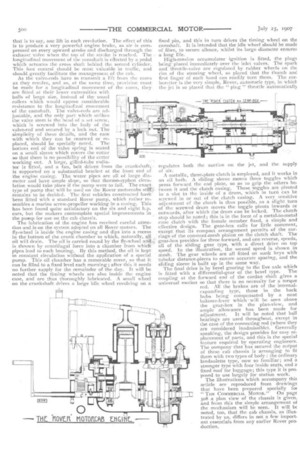
The most noticeable feature of the design is the fact that The engine, clutch, and gear casings, are bolted together to form one strong unit, and this is then used as part of the main frame; it carries the front axle without any assistance from the frame members proper. The lattex are of the sandwich type; each consists of two steel flitch-plates with ash between them. The longitudinal members are braced by three strong cross members, one immediately behind the engine, another at the back of the gear-box, and a third at the extreme rear end of the chassis. Altogether the frame is very light, but strong for its weight. The frame does not extend any further forward than the dashboard. It is true that a steel angle carries the bonnet and radiator and would, at first sight, appear to be an extension of the frame, but in reality this angle-iron is only there for the purpose of supporting the radiator and the wooden sideboards under the edge of the bonnet. It has nothing to do with the weight-carrying portion of the frame; it is only supplementary to it.
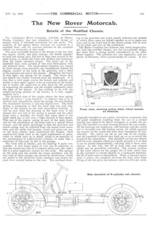
The sectional view of the engine shows the front spring (with the leaves "cross hatched " to indicate that it is :n section) and, immediately above the spring, the pin forming the attachment between it and the engine case. The front spring is transverse so that the front axle can rock relatively to the chassis as the road inequalities demand. It will be seen from the drawing of the front view of the chassis that one end of the spring is pinned and the other hung from a shackle; the action that takes place if one fnont wheel has to ride over a high obstacle is also shown. This use of the engine casing as part of the main frame and for the attachment of the front axle is a special Rover feature, and the great advantage is that the gear-box and clutch casing may be unbolted from the frame cross members, and the whole unit (engine, clutch and gear) run out, on the front wheels, from underneath the chassis. Such construction lends itself to the rapid replacement of parts, either as whole units or in detail, which is so essential to the maintenance of public-service vehicles, in order that a minimum of time may be lost in the garage.
The front axle is tubular, and the-steering is quite irreversible. A very large angle of lock Can be obtained, so that the chassis can turn in a roadway about 22ft. fin, wide ; this is a most important feature for cab work. The springs on the back axle. are outside the frame members, and the rear ends of these springs are carried by dumb-irons, which are bolted to the sandwich frame members and project beyond them several inches to the rear. The sectional draw
ing of the gear-box and clutch clearly indicates the method by which these cases are bolted together so as to make one unit, and at the front end of the clutch casing will be seen the fly-wheel and part of the crankshaft. The Rover Company has hitherto only listed single-cylinder, and four-cylinder chassis, but this two-cylinder design has more than a strong family resemblance to the other Rover engines. The cylinders are cast separately, and are g7mm. in diameter, with a piston-stroke of tiomm. It was
originally intended to use a plain, two-throw crankshaft, but the great steadiness resulting from the use of a central bearing has induced the Rover Company to modify the design and introduce an extra bearing between the two cranks. All the bearings are single-row, ball bearings and the centre one is threaded over the leading crank, for which purpose the corners of the crank-web have been chamfered off considerably. The valves are all on one side of the engine, and the camshaft is placed very high up, so as to reduce the length of the valve-stems. The camshaft carries two sleeves (one for each cylinder) which are rigidly secured to it so that it can be moved longitudinally, carrying with it these cam. sleeves. In this way, the lift •of both inlet and exhaust valves can be accurately controlled. The normal position of the cams allows for the proper lift of both valves but, as the camshaft is moved slightly in a backward direction, the lift of both valves is diminished. When a forward movement is given, the camshaft prevents the inlet valve from lifting at all, but gives the exhaust valve two lifts per cycle,
that is to say, one lift in each revolution. The effect of this is to produce a very powerful engine brake, as air is compressed on every upward stroke and discharged through the exhaust valve when the top of the stroke is reached. The longitudinal movement of the camshaft is effected by a pedal which actuates the cross shaft behind the second cylinder. This foot control should be most valuable in traffic, and should greatly facilitate the management of the cab. As the valve-rods have to transmit a lift from the cams as they revolve, and as, at the same time, provision must be made for a longitudinal movement of the cams, they are fitted. at their lower extremities with balls of large size, instead of the -usual rollers which would oppose considerable resistance to the longitudinal movement of the camshaft. The valve-rods are adjustable, and the only part which strikes the valve stem is the head of a set screw, which is screwed into the body of the valve-rod and secured by a lock nut. The simplicity of these details, and the ease with which they can be renewed or re placed, should be specially noted. The bottom end of the valve spring is seated on a small sleeve which covers the cotter so that there is no possibility of the cotter working out. A large, gilled-tube radiator is fitted, and a fan, belt driven from the crankshaft, is supported on a substantial bracket at the front end of the engine easing. The water pipes are all of large diameter and have ample slope, so that thermo-syphon circulation would take place if the pump were to fail. The exact type of pump that will he used on the Rover motorc.abs remains to be decided. The first vehicles constructed ha been fitted with a standard Rover pump, which rather resembles a marine screw-propeller working in a casing. This has been found quite satisfactory on the six and eight lip. cars, but the makers contemplate special improvements in the pump for use on the cab chassis.
The lubrication of the engine has received careful attention and is on the system adopted on all Rover motors. 'The
fly-wheel is inside the engine casing and dips into a recess in the bottom of the crank chamber to which, naturally, all oil will drain. The oil is carried round by the fly-wheel
is thrown by centrifugal force into a chamber from which pipes lead to each bearing. By this method, the oil is kept in constant circulation without the application of a special pump. This oil chamber has a removable cover, so that it can be filled to a fixed level each morning ; after this it needs no further supply for the remainder of the day. It will be noted that the timing wheels are also inside the engine case, and are thus thoroughly lubricated. A small wheel on the crankshaft drives a large idle wheel revolving on a fixed pin, and this in turn drives the timing wheel on the camshaft. It is intended that the idle wheel should be made of fibre, to secure silence, whilst its large diameter ensures a long life.
High-tension accumulator ignition is fitted, the plugs being placed immediately over the inlet valves. The spark and throttle-valve are regulated by rubber wheels on the rim of the steering wheel, so placed that the thumb and first finger of each hand can readily turn them. The carburetter is the very simple, Rover, automatic type, in which the jet is so placed that the " plug " throttle automatically regulates both the suction on the jet, and the supply of air. A metallic, three-plate clutch is employed, and it works in an oil bath. A sliding sleeve moves three toggles which press forward the end plate, so as to grip the others be tween it and the clutch casing. These toggles are pivoted in a slot in the inside of a drum, which in turn can he screwed in or out of the clutch casing. A very sensitive adjustment of the clutch is thus possible, as a slight turn of the screwed drum moves the toggle pivots inwards or outwards, after which the drum can be locked. The clutch stop should be noted; this is in the form of a metal-to-metal cone clutch with the female member fixed, a simple and effective design. 'The gear-box calls for little comment, except that its compact arrangement permits of the carriage of the constant-mesh pinion on the clutch shaft. The gear-box provides for three forward, and one reverse, speeds, all of the sliding gear type, with a direct drive on top speed. In the illustration, the second speed is shown in mesh. The gear wheels are all fitted on sunk keys with tubular distance-pieces to ensure accurate spacing, and the sliding sleeve is built up in the same way. The final drive is by bevel gearing to the live axle which is fitted with a differential-gear of the bevel type. The coupling at the forward end of the cardan shaft gives a universal motion so that there is no necessity for a torque rod. All the brakes are of the internal expanding type; those in the back
hubs being compensated by a neat balance-lever whichwill be seen above
the gear-box in the plan-view, and ample allowance has been made for adjustment. It will be noted that ball bearings are used throughout, except in the case of the connecting rod (where they are considered inadmissible). Generally speaking, the design provides for easy re placement of parts, and this is the special feature required by operating engineers. The company that has secured the output of these cab chassis is arranging to fit them with two types of body : the ordinary landaulette type, now so familiar; and a stronger type with four inside seats, and a fixed roof for luggage; this type it is proposed to use largely for station work. The illustrations which accompany this article are reproduced from drawings that have been prepared specially fot "THE COMMERCIAL MOTOR." On page 5o8 a plan view of the chassis is given, and from this the simple arrangement of the mechanism will be seen. It will be noted, too, that the cab chassis, as illustrated by us, differs in not a few important essentials from any earlier Rover production.