


Patents Completed.
Page 24
If you've noticed an error in this article please click here to report it so we can fix it.
CARBU It Jr I I' E R.—Southey and Others.—No. 19,096, dated 27th August, 1906.—A is the carburetter and B the float-feed chamber which determines the supply Of fuel to the displacement vessel (D); out of this the requited quantity is ejected by means of the displacement rod (E). The displacement rod (E) is actuated by a lever (K) which, in turn, is operated by movement of the inlet valve (G), Tie carburetter is worked by the lifting of the. inlet valve (P) of the engine by means of the rod (I), which passes up one of the vaporising tubes (N) and opens the inlet valve (G) simultaneously with the opening of the inlet valve(P). The quantity of fuel supplied is determined by thit stroke of the rod_ (E), which is adjusted, as required, by means of a wedge (C), which is pushed under the lever (K), and serves to stop .it. after any desired portion of the stroke has taken place. Pyre air only is taken in through the induction pipe (R) of the engine, a small quantity also being taken in with the oil through the ports (S). The fuel is delivered direct into -the combustion space (0), and dots not„pass through a. length of induction pipe where it would be liable to condense. This facilitates starting when the engine is cold. The tubes (N) project into the combustion space (0), and thereby take up the necessary heat to effect vaporisation. These tithes, being exposed under the body of the carburetter, may he initially heated by a blow lamp. In a modified construction, a fan is provided within the mixing chamber, this fan being operated by the suction of the engine, and itself operating means for displacing the required quantity of fuel from a displacement vessel.
LIQUID FUEL REGULATORS.Clarkson.—No. 19,106, dated 27th August, 1906.—This invention provides a regulator for liquid-fuel burners, in which two metallic members, having different coefficients of expansion, operate under the varying temperature of steam produced in the generator, to control the flow of fuel to the burner. A tube (Al has its ends secured in blocks (B, Cl) to which are connected steam inlet and outlet pipes (131, Cl). In the block (B) is aeranged tube (D) having one end closed by a plug (DI), and the other seCliree, to a flange (DI). Within the tube (D) is a rod (E), whose co-efficient of expansion differs from that of the tube (D). The rod (E) is secured, at one end, to the plug (DI), and the other end lies flush with the flange (D2) at normal temperature. Secured to the block (B) through the flange (D2) is a valve casing (Fi) having fuel inlet and outlet pipes (K, L).. Within the cas ing (171) is a valve (G) which is normally open, and has a cone end (Cl) which is forced against its seating by a spring (II). A notch (03) is cut in the side of the cone (02), so that, when the valve is completely elosedesufficient fuel can pass to keep the burner alight. A gauge (M) is connected to the fuel outlet ptpe (L) to indicate the amount of fuel passing to the burner. Arranged in a hole (F5) within the casing (FI) ii an 'interchangeable rod (I) having its end rounded.„This rod forms the operating cortnectiqi between the thermostatic members (El, E) and the valve (G). It will be seen that the varying temperature of the steam passing through the tube (A), and the corresponding expansion of the members (D, E) will operate the valve (G), and so regulate the flow of fuel to the burner.
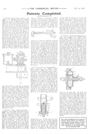
AUTOMATIC VAPORISERS.— Boult (Scheibert).No. 22,611, dated 12th October, 1906e-eThe fuel is first atomised and subsequently used to carburate air. The vaporising casing (a) is secured by screwing it to the pipe: (b) for the supply a the medium to be vaporised, Within the casing is a pipe (c) on which is mounted a disc (d). At the top of the pipe (c) a valve (1) is arranged, which is normally kept closed by a spring (le). In operation, during the suction period of the engine, the valve (1) is lifted from its seat in opposition to the spring (k) so that liquid fuel is drawn in. The liquid is atomised on escaping from the valve. Owing to the lifting of the valve, the pipe (c) is, at the same time, lifted in opposition to the action of a spring (f), and the disc (d) is thus lifted from the per forated plate (g). In this way, it is rendered possible for air to enter through holes (p) in the plate (g), the air rising be. tween the pipes (8, c), and through an opening (p) in the disc (d) between the pipe (c) and casing (a). The opening (25) is arranged in the disc (c7): between two openings of the plate (g), so that, when the valve (i) is closed, and the disc tests on the plate (g), DO air can come in from below. The strength of the springs (k, j") is arranged so that the opening of the valve (i), as well as the lift of the disc (d), is in such proportion to the strength of the suction of the engine that the exact quantity of explosive fluid required is drawn in. The casing is provided with a slot (m), and an annular valve (a) with slots is arranged at that point to control the size of the inlet open. ing for the air required for combustion.
CLUTCH.—George Anderson and Co , Ltd., and Another.—No. 17,945, dated 10th August, 1906.—The female portion of the clutch, which may also act as a fly-wheel, is made in two parts (3, 1), with internal cane faces (5, 6), the two parts (3, 4) being bolted together, when the inner cones (7, 8) are in position. One cone (5) is fixed to the crankshaft (10) of the engine, and the other cone (6) has a projecting hollow boss (11). The inner male cones (7, 8) each engage with their cones (5, 6) independently of each other. The inner cone (7) is bolted to the shaft (13), and the inner cone (8) is provided with a sleeve (14). The inner cones (7, 8) ere coupled to rotate together, by telescopic studs (15), spiral springs (16) tending to keep these cones apart and the clutch in operation. On the sleeve of the inner cone (8) is a ring composed of a part (18) carried by the sleeve, and a part (17) mounted on ball-thrust bearings : there is a similar ring (19) carried by, and fixed to, the shaft (13). To throw the clutch out of action, these two rings cats be forced apart by rollers (20) carried by an arched crank or lever (21) which is supported in suitable bearings on the engine frame. The arched crank may be connected to, and actuated by, a foot pedal. The operating rollers (20) are arranged so that one cone is released before the other, and, on engaging again, one cone engages before the other, thus allowing a certain amount of slip ; this makes an engagement gradual and without shock. The chamber formed by the parts (3, 4) may be filled with oil. The thrust of the helical springs is entirely taken up within the two component parts of the flywheel and is, therefore, self-contained.