


A Complete Analysis of How Chains Act.
Page 12
Page 13

Page 14
If you've noticed an error in this article please click here to report it so we can fix it.
First Article : The Block Chain.
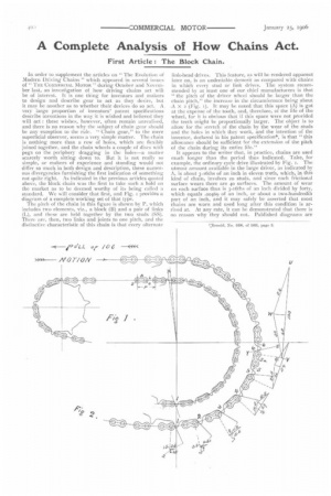
In order to supplement the articles on " The Evolution of Modern Driving Chains " which appeared in several issues of " THE COMMERCIAL MOTOR " during October and November last, an investigation of how driving chains act will be of interest. It is one thing for inventors and makers to design and describe gear to act as they desire, but it may be another as to whether their devices do so act. A very large proportion of inventors' patent specifications describe inventions in the way it is wished and believed they will act : these wishes, however, often remain unrealised, and there is no reason why the subject of chain gear should be any exception to the rule. " Chain gear," to the mere superficial observer, seems a very simple matter. The chain is nothing more than a row of holes, which are flexibly joined together, and the chain wheels a couple of discs with pegs on the periphery dragging in the holes—a matter scarcely worth sitting down to. But it is not really so simple, or makers of experience and standing would not differ so much in both design and description, these numerous divergencies furnishing the first indication of something not quite right. As indicated in the previous articles quoted above, the block chain was the first to take such a hold on the market as to be deemed.worthy of its being called a standard. We will consider that first, and Fig. i provides a diagram of a complete working set of that type.
The pitch of the chain in this figure is shown by P, which includes two elements, viz., a block (B) and a pair of links (L), and these are held together by the two studs (SS). There are, then, two links and joints to one pitch, and the distinctive characteristic of this chain is that every alternate link-head drives. This feature, as will be rendered apparent later on, is an undeniable demerit as compared with chains
in which every stud or link drives. The system recommended by at least one of our chief manufacturers is that " the pitch of the driver wheel should be larger than the chain pitch," the increase in the circumference being about A X 2 (Fig. 1). It may be noted that this space (A) is got at the expense of the tooth, and, therefore, of the life of the wheel, for it is obvious that if this space were not provided the teeth might be proportionally larger. The object is to allow for the stretch of the chain by the wear of the studs and the holes in which they work, and the intention of the inventor, declared in his patent specification*, is that " this allowance should be sufficient for the extension of the pitch of the chain during its entire life." It appears to the writer that, in practice, chains are used much longer than the period thus indicated. Take, for example, the ordinary cycle drive illustrated by Fig. 1. The utmost amount available in the large driver, as indicated by A, is about 3-16ths of an inch in eleven teeth, which, in this kind of chain, involves 20 studs, and since each frictional surface wears there are 40 surfaces. The amount of wear on each surface thus is 3-t6ths of an inch divided by forty, which equals .00469 of an inch, or about a two-hundredth part of an inch, and it may safely be asserted that most chains are worn and used long after this condition is arrived at. At any rate, it can be demonstrated that there is no reason why they should not. Published diagrams are generally of small wheels only, in which cases the spare pitch (A) is from two to three times the value; and here there is an inconsistency, for the total allowance pitch (A) is much the same in a large wheel as in a smaller wheel. If, therefore, the driver in the present case is 21 times as great as the driven, then the chain will have run out of pitch 2 times as soon. Of course, for the same reason, the smaller wheel will be proportionately sooner worn out, since it
revolves 21 times as often. That, however, does not alter the pitch much : what it does alter is, mostly, the opposite to compensatory. But what has to be sought, in this analysis, is to determine if this gear acts as intended. In the first place, it is claimed that only one tooth and link engage at one time, and that ii is an essential feature, in the Form of the tooth, that it should slope sufficiently to admit, during the revolutionary period of one pitch, of the next link's sliding round the drum the equivalent of the difference of pitch between chain and wheel. Now, since the rise of the outgoing link head is so little during this period, it follows that the slope must be considerable; such, in fact, as to accelerate its slipping materially. As to this matter of slipping off the tooth, there are several elements which influence it. They are (a) the degree of slope, (b) the frictional resistance, (c) the tautness of the free chain between the wheels, and (d) the centrifugal form due to rotary motion. The slacker the chain the greater the angle of tooth, or the quicker the spied the sooner the slip, and the lighter the load under speed the sooner the slip. The speed has not to be so very great for the point to be reached at which nearly the whole of the links engaged with the wheel can be regarded as flying off the drum, and automatically taking up a position where pitch of wheel and chain are in harmony. This, of course, is possible only after the pitch of the chain has worn larger than the wheel, and is the time when both chain and wheel are working at their best, and this should be the aim of the designer. But in this kind of gear, where only every alternate link drives or resists, there is a counteracting eement which accentuates the increase of pitch, for, as soon as the chain leaves the drum radially, the two links concerned in one pitch form a straight line under tension and 'are, therefore, longer in pitch than when wrapped round the wheel drum. Here we haVe the peculiarity which constitutes the great demerit of this type of gear.
Let it be supposed that the centrifugal force and the frictional resistance against the link-head slipping up the tooth balance each other; it is then possible to construct a diagram of forces in a simple manner. Assuming the force transmitted to be equal to too in the direction of the links embracing the tooth 1. Since the surface of the tooth is at something less than a right-angle with the pull of that link, the link will tend to slip off the tooth; and since, by this diagram, there is nothing to stop the link from doing so, but, rather, on the contrary, its own weight and that of the loose part of the chain helning it, it is is seen that even link 2 cannot retain its position—it slips
obvious that the diagram is wrong and the supposed pc:salon an impossible one. This means that the gear will not do what it was designed and expected to do by the inventor. What really happens is that the link slides off tooth i until it meets with sufficient resistance to stop it.
The writer is of opinion that Fig. 2 provides the true explanation of what occurs. Link I has slipped, and has allowed link 2 to slide round the drum on to tooth 2 ; but it
off part way like the others. Each toto:1, 11;wevvr, is ab7;orbing a certain amount of pull, which must be measured. Since the full strain is too, and the first resistance in the example under consideration is met at tooth 6, the full strain is also on link 6; further, since the resisting surface of the tooth is on the line V Z., and the only available force to ..resist its slipping off is the next link, the triangle U V NV represents a parallelogram of the three forces involved at this point (V being the pin centre connected by the dotted line). The line U V represents in magnitude and direction the strain brought on the pin by link 6; XV V represents the pressure brought on the surface of the tooth at rightangles to its surface; and U XV the amount transmitted to link 5. The deflection caused by the non-driving end of block 5a, which does not affect the main question, is ignored for simplicity. It will be found, on treating the other
driving points in like manner that they form an approximate compound depreciation or asymptote; but, since the Point of touch on the teeth varies slightly, the angle also varies slightly, and the gradual reduction varies in proprtion. It should be noted that the diagram lines at right angles to the teeth, though they represent the pressure on the teeth, do not represent the turning moment, which should form a tangent from the point in question, which is not shown by V W.
If, therefore, we draw a line at right-angles to U V from the point W, the lower part of U V will represent that turning moment; so if any reader wishes to prove the set of triangles and to see if the collertive turning momen,son the several teeth come to the main strain, they will lind it so-48+26+14+7+3+ 2= 100. It might be added 1.e:or: leaving this subject that this kind of driver wheel is suspect, if not guilty, of the hook deformation of tooth. Where the teeth are originally high in angle, the slipping will be delayed and curtailed, and this curtailment, at the beginning of the wheel's life, results in wear to only a very small part of the root of the tooth, because the link never touches higher up. The more this takes place the more it is aggravated, and the worn hook tooth is a natural consequence.
The one-tooth drive theory is evidently wrong, and till
declaration that the point at which we are advised to discard the gear is the point at which it is just beginning to work its best remains. IL is supported by an examinatiot of the case of a well-worn gear, in which the chain has stretched more than twice that recommended for rejection, and still is by no means at the end of its life. Fig. 3 represents such a gear; it is not a supposed example, but an actual worn specimen, which is before the writer at the moment. As in Fig. 2, the main chain strain is represented by too. It will be observed that the top tooth in this case gets the brunt of the work. We start, as before, by forming a triangle with lines, representing, in both magWtude and direction, the three forces upon stud t. The line marked 54 represents the pressure upon tooth z, which, of coarse, is at right-angles to the slope of that tooth at the
point of contact. Line 48 represents the amount of force transmitted to the next tooth, and that part of the main line cut off to the right of the short vertical line, and marked 53, represents the turning moment on the tooth. As in the previous diagram, triangles representing the strain on the following working link heads and their studs are formed. In this case, however, the triangles have been connected and thereby made still more diagrammatically representative of the strains on the chain, and the figures representing the turning moments have been extended in column form, and added up to prove the general accuracy. The last figure (2) cannot he said really to bear on the tot:th, because there must be a certain amount of counter-strain coming from the loose part of chain which hangs between the wheels. These figures are true, then, subject to reduction by that amount, which, of course, is comparatively insignificant. It may also he observed that there is a certain amount of automatic pitch in this gear, and it was this discovery that led to the deliberate designing of the automatic pitch gear; but this is a matter to be dealt with later on, when another type of gear is discussed. The roller chain will be considered in
next week's article. HERBERT Gomm.