


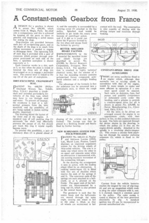
A Constant-mesh Gearbox from France A DESIGN for a gearbox is
Page 50
If you've noticed an error in this article please click here to report it so we can fix it.
shown in patent • No. 638,301, which comes from A. Magis, Paris: Its chief aim is compactness, and this is achieved by keeping all the parts as short as possible and 'emplOying a noVel means for sliding the dogs.
Dog-clutches are provided between each pair of 'co-operating gears, and as the depth of the dogs is so small, little sliding movement is needed to engage or disengage them. The operating fork of each dog is provided with a pair of trunnions which -project through camplates positioned on each side of the box; a specimen cam-plate is shown separately at 1.
• Each trunnion works in a slot, such as 2, so that when the plate is raised or lowered the three sets of dogs are re-arranged so as to engage a particular ratio. The control lever is linked to the top (3) of the pair of cam-plates.
DIRT-EXCLUDING CRANKSHAFT SEAL.
PATENT No. 640,299 (WillysOverland Motors Inc., Toledo, Ohio. U.S.A.) describes a crankshaft seal intended particularly for vehicles of the Jeep type, which may have to run through mud and water. To prevent oil seepage, the crankcase is kept at a subnormal pressure from the inlet manifold, and the possibility of dirt lacing sucked in makes sealing
doubly, important. ••• The drawing shows the layout of the -front .end of the engine. A standard type of soft packing ring (1) surrounds the shaft and effectually prevents the escape of oil, but should grit reach this ring it would rapidly become worn.
'To'preyent this possibility, a pair of stationary discs (2) is placed ahead of
BETTER MOULDED BRAKE FACINGS
'IMPROVEMENTS 'in the I material for moulded brake and Clutch facings are described in patent No 639,900, by Harvel Research Corporation, Irvington, New Jersey, U.S.A. The specification is couched in highly technical' chemical terms, but the essence of it is that the moulding mixtare contains polymerized furanc compound, powdered asbestos and a suitable binding agent.
The advantage of the formula is that the substance can be pre-cured into a semi-plastic state, in which the rough shaping of' the articles can be performed. The facings ' can then be placed in a finishing mould and finally fixed by further heating. •
NEW SUSPENSION SYSTEM FOR FOUR-WHEELERS
-DATENT No. 640,121 (J. Naylor
and Atkinson Lorries [1933], Ltd., Marsh Lane, Preston, Lanes) discloses an improved suspension system for the driving wheels of twin-axled vehicles. The aim is to make one wheel move the other in an equal and opposite sense when an obstruction is encountered, without causing excessive movement of the connecting linkages.
In the drawing the arrangement is seen in action, with the leading _wheel lifted by an obstruction. A rocking centre-beam (1) is fitted with two sets of shackles which receive the ends of the springs (2 and 3). The outermost ends of the springs are each attached to a bellcrank, as at 4, pivoted on the frame. The upper ends of the bellcranks are interconnected by a long rod (5), which is alsopivoted to the central beam.
The geometry is such that the centre beam and the belt-cranks are moved through the same angle, causing one wheel to fall as the other is lifted, so that all wheels are maintained in fell contact with the road. The construction is also capable of dealing with the driving torque and reactions through braking.
CONSTANT-SPEED DRIVE FOR AUXILIARIES
THERE are many auxiliaries fitted to an engine which, although they normally run at varying speeds in accordance with that of the engine, would he more simple to make and more efficient in operation if a constant speed could be ensured. Such units as dynamos,fans, fuel pumps and possibly compressors or exhausters come under this heading, and a scheme to provide
• a constant-speed drive for all is shown in patent No. 639,949, by -Eaton Manufacturing Co., Cleve land, Ohio, U.S.A. • . All the units to be ,driven are arranged around the engine in an approximate circle, with their pulleys in line, so that common belts can be used. The belts are operated through the device shown in the drawing, in which the pulley (I) is free on the engine-driven spindle. Attached to the spindle is a revolving electro-magnet (2). This creates a circular field reachMg out through the annular enclosing armature (3), which is fixed to the pulley.
Current from the vehicle batteries reaches the magnet by way of slip-rings (4) and sets up magnetism which tends to drag the outer armature with it, and, it, is claimed, imparts a constant speed to the pulley. The outer casing is vaned to dispose of the heat generated electrically by slip. A standard ignition key (5) can be incorporated to prevent unauthorized tise.