 1
1 2
2 3
3 4
4 5
5 6
6 7
7 8
8 9
9 10
10 11
11 12
12 13
13 14
14 15
15 16
16 17
17 18
18 19
19 20
20 21
21 22
22 23
23 24
24 25
25 26
26 27
27 28
28 29
29 30
30 31
31 32
32 33
33 34
34 35
35 36
36 37
37 38
38 39
39 40
40 41
41 42
42 43
43 44
44 45
45 46
46 47
47 48
48 49
49 50
50 51
51 52
52 53
53 54
54 55
55 56
56 57
57 58
58 59
59 60
60 61
61 62
62 63
63 64
64 65
65 66
66 67
67 68
68 69
69 70
70 71
71 72
72 73
73 74
74 75
75 76
76 77
77 78
78 79
79 80
80 81
81 82
82 83
83 84
84 85
85 86
86 87
87 88
88 89
89 90
90 91
91 92
92 93
93 94
94 95
95 96
96 97
97 98
98 99
99 100
100 101
101 102
102 103
103 104
104 105
105 106
106 107
107 108
108 109
109 110
110 111
111 112
112 113
113 114
114 115
115 116
116 117
117 118
118 119
119 120
120 121
121 122
122 123
123 124
124 125
125 126
126 127
127 128
128 129
129 130
130 131
131 132
132 133
133 134
134 135
135 136
136 137
137 138
138 139
139 140
140 141
141 142
142 143
143 144
144 145
145 146
146 147
147 148
148 149
149 150
150 151
151 152
152 153
153 154
154 155
155 156
156 157
157 158
158 159
159 160
160 161
161 162
162 163
163 164
164 165
165 166
166 167
167 168
168 169
169 170
170 171
171 172
172 173
173 174
174 175
175 176
176 177
177 178
178 179
179 180
180 181
181 182
182 183
183 184
184 185
185 186
186 187
187 188
188 189
189 190
190 191
191 192
192 193
193 194
194 195
195 196
196 197
197 198
198 199
199 200
200 201
201 202
202 203
203 204
204 205
205 206
206 207
207 208
208 209
209 210
210 211
211 212
212 213
213 214
214 215
215 216
216 217
217 218
218 219
219 220
220 221
221 222
222 223
223 224
224 225
225 226
226 227
227 228
228 229
229 230
230 231
231 232
232 233
233 234
234 235
235 236
236 237
237 238
238 239
239 240
240 241
241 242
242 243
243 244
244 245
245 246
246 247
247 248
248 249
249 250
250 251
251 252
252 253
253 254
254 255
255 256
256 257
257 258
258 259
259 260
260 261
261 262
262 263
263 264
264 265
265 266
266 267
267 268
268 269
269 270
270 271
271 272
272 273
273 274
274 275
275 276
276 277
277 278
278 279
279 280
280 281
281 282
282 283
283 284
284 285
285 286
286 287
287 288
288 289
289 290
290 291
291 292
292 293
293 294
294 295
295 296
296 297
297 298
298 299
299 300
300 301
301 302
302 303
303 304
304 305
305 306
306 307
307 308
308 309
309 310
310 311
311 312
312 NEW CHASSISLESS kT BUS
Page 94
Page 95
If you've noticed an error in this article please click here to report it so we can fix it.
L.T.E. Design Doubledecker with Engine Removable on Sub-frame, Coil Springs and Two pedal Control
FACED with the task of replacing London's trolleybuscs in about three years' time, and the subsequent replacement of the R.T.-type double-deck motorbuses, the London Transpprt Executive have designed a new oil-engined bus, the prototype of which is to be seen at the Commercial Motor Show.•
The new bus has been evolved by the L.T.E. road-vehicle engineers, led by Mr. A. A. M. Durrant, C.B.E., chief mechanical engineer (road services). The prototype has been constructed in association with A.E.C., Ltd., and Park Royal Vehicles, Ltd., and is exhibited on the A.E.C. stand (Si).
To design an all-metal vehicle to carry 64 seated passengers in comfort within an overall size of 27 ft. by 8 ft,
Mr. Durrant and his team had to look well ahead of current practice. -Additional requirements were that the loaded weight should not exceed that
of the existing 56-seat vehicle and that reliability, long life and ease of maintenance should not be sacrificed.
One of the lightest forms that such a vehicle can take is the chassisless type, and by using light alloys, glass fibre and other weight saving materials, an unladen weight of approximately 6 tons 14 cwt. has been achieved. The wheelbase is 16 ft. 9 in.
Removable Sub-frames
The body structure serves as the main load-carrying unit, with sub-frames to support the mechanical units at front and rear, as no conventional chassis frame is used. The present practice of using easily removable bodies, which are interchangeable, is not convenient with the new design, so the sub-frames are made to withdraw for servicing.
Other innovations include the use of independent front-wheel suspension with coil springs, a new coil-spring suspension system at the rear, and twopedal control.
The main vehicle structure is fabricated from high-duty aluminium alloy. The underframe consists of rigid I-beam cross-members and the lower-saloon body is made up of H-section extruded alloy pillars. Sheet stress-panels, from waist to skirt, are riveted to the inside of the pillars and bolted between the crossbearers and pillars.
Exterior panelling of aluminium sheet is butt-jointed and blind-riveted to the framing without vertical cover strips, the panels being fitted internally to minimize replacement difficulties in the event of damage.
Floor bearers, similar to the main cross-members, extend from pillar to pillar and form the anchorage of the upper-saloon pillars, which are made of extruded alloy in H-form. The stress panels of the upper saloon, not being so subject to accidental darriage, are fitted externally.
The upper-roof structure is of squaresection alloy tube with rived overlapped exterior panelling in alloy sheet, as are the floors and ceilings. The upper-deck floor is laid in three fiat sections, instead of in the usual radius. Floor cover panels of chequered aluminium plate are fitted to both decks.
The front bulkhead is constructed of channel and angle members to which a skin of aluminium alloy is riveted. Two robust buttresses, built on to the front face of the bulkhead, form the anchorages for the forward front sub-frame attachment bolts. The rear anchorages of the front sub-frame are built into the front main cross-bearer.
The engine, steering gear and front suspension units are carried on the forward sub-frame, which consists of two pressed channel-section longitudinal members extending forward from the front bulkhead and attached at four points. In plan view, the members converge at the front, being anchored to the body sides and reduced to normal chassis width at the front.
They are joined by two crossmembers; one carries the main engine mountings and the independent frontsuspension units, and the other. which joins the front ends of the longitud supports the front of the engine.
The front sub-frame assembl removed for servicing by liftiN main body structure at jacking p incorporated in the driver's rec step and a similar step at the near The attachment bolts are then connected and the running un wheeled forward on the front wh.
The main members of the rear frames consist of two " spectz radius arms of pressed channel sec pivoted at their front ends on rt. bushes from brackets on the body. radius arms extend backwards an' bolted to an I-section-member extends across almost the whole of the vehicle and reacts against thc springs.
The engine is the proven A.E.0 litre direct-injection unit which dev 125 b.h.p. at 1,800 r.p.m. The ab: of a conventional frame and leaf sp enables it to be mounted toward near side. The main engine mou is at the centre of the power unit consists of two rubber sanc assemblies placed to form a V abot longitudinal axis of the engine.
A third mounting point is in the of a large circular rubber unit en front of the cylinder block and ca on the front cross-member, folic current A.E.C. practice.
Radiator Behind Engine
The water pump and fan are mot as a sub-unit with the radiator an' driven from an extension on the dyr armature. The radiator has an al horizontal position under the main to the right of and behind the en Transmission is through a coupling and independently mot epicyclic gearbox, having the t bands operated by direct hydraulic
sure. Gear selection is by ele hydraulic valves operated from a which, although operating electrica cults only, is identical with that usc the existing vehicles. with pre-sele gearboxes. The gearhange ped thus eliminated, providing two-1 control.
Steering is by an A.E.C. worm
unit mounted on the sub-frame. he rear axle is located laterally by .ansverse radius rod and has fully Ling axle shafts. The driving unit is :t towards the left-hand side and al-bevel gears give a ratio of :
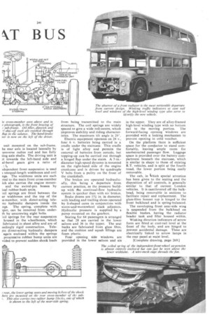
idepenclent front suspension is used unequal-length wishbones and coil ngs. The wishbone units are each )ted to the main front cross-member ich also carries the engine mount and the swivel-pin bosses by ical rubber-bush units.
:oil springs are fitted between the er wishbones and the top of the is-member, with direct-acting telelie hydraulic dampers inside the ngs. The spring, complete with iper, can be removed from underth by unscrewing eight bolts.
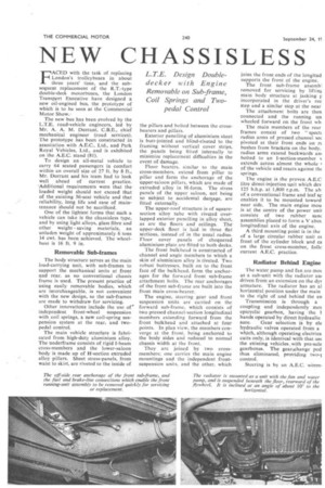
:oil springs for the rear suspension housed in the wheelboxes, which fabricated in sheet alloy and are of eedingly rigid construction. Telepic direct-acting hydraulic dampers again enclosed within the springs . progressive rubber bump units are vided to prevent sudden shock loads from being transmitted to the main structure. The coil springs are widely spaced to give a wide roll-centre, which improves stability and riding characteristics. The maximum tilt angle is 29'.
Electric equipment operates on 24 v., four 6 v. batteries being carried in a cradle under the staircase. This cradle is of light alloy and permits the removal of batteries from outside, but topping-up can be carried out through a hinged flap under the stairs. A 7-in.diameter high-speed dynamo is mounted on the right-hand side of the engine crankcase and is driven by quadruple V belts from a pulley on the front of the crankshaft.
The brakes are operated hydraulically, this being a departure from current practice, as the pressure buildup with fie continual-flow hydraulic system is quicker than with air brakes.
Brake drums are 151 in. in diameter; with leading and trailing shoes operated by S-shaped cams in conjunction with worm-and-wormwheel slack adjusters. Hydraulic pressure is supplied by a pump mounted on the gearbox.
Seating for 64 passengers is arranged so that 28 are carried in the lower saloon and 36 in the upper. The seat backs are fabricated from glass fibre. and the cushion and squab fillings are foam plastic.
Four opening side windows are provided in the lower saloon and six in the upper. They are of alloy-framed high-level winding type with no bottom rail to the moving portion. The forward-facing opening windows are provided with a locking mechanism to prevent opening in cold weather.
On the platform there is sufficient space for the conductor to stand comfortably, leaving ample room for unobstructed passenger flow. Luggage space is provided over the battery compartment beneath the staircase, which is similar in shape to those of existing R.T. vehicles, and is split at the fourth tread, the lower portion being easily removable.
The cab, in thich special attention has been given to the seating and the disposition of all controls, is generally similar to that of current London vehicles. It is cantilevered off the bulkhead, being removable in sections to facilitate repair and replacement. The glass-fibre bonnet top is hinged to the front bulkhead and is spring-balanced.
The enveloping front near-side wing is suspended from the bulkhead on flexible bushes, having the radiator header tank and filler housed within.
Winking direction indicators of arrow form are fitted at cant-rail level at the front of the body, and are hinged to prevent accidental damage. These are electrically linked to arrow lamps in the rear panel at waist 'level.
[Complete drawing, page 269.]