


PATENTS SUMMARIZED.
Page 22
If you've noticed an error in this article please click here to report it so we can fix it.
Vickers Rotary Engine.
The fact that Vickers, Ltd., is responsible in the main for the patent rotary internal-combustion engine described in SpecificationNo. 118,424 will add not a -little interest to 'that which is normally evoked by any design of this type of • prime mover, 'asAnetwithstanding the many and varied fruitless attempts 'which have been made to design a satisfactory rotary engine 'Ahem are still many who believe that success will eventually be the, portion of some fortunate or ingenious inventor. That a concern like . Vickers, Ltd., is taking an active interest in this particular design is almost sufficient to prove it to be better than the average run of these inventions.
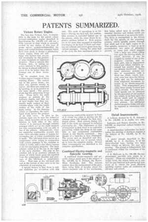
In its simplest form the Vickers engine consists of three rotating drums. The central one is the power drum • the other two operate merely as valves. All three are connected by-gearing, so as to revolve at the same speed. The power drum has two projecting Wings only. These serve the same purpose as pistons in the ordinary engine, 'and they arc of such length that they constantly make contact at their extreme edges with the inside surface of the walls of the -.main Casing. In the drawing which we reproduce, the righthand drum serves the purpose of an inlet valve. In plan on the extreme right can be seen the induction pipe, which branches out so as to supply mixture to both sides of the valve, whence it, is conveyed through suitable passages which are at the right moment put into communication with one side of one of the pistons. Alternatively, when riot supplying combustible mixture this mime valve provides means of ingress .for scavenging air, of which Considerable use is made. The left-hand drum serves as a compression valve, actlng in conjunction with certain passages in the chamber in which it. works, and it also allows ingress 'of air for scavenging purposes. The main exhaust outlet is on the top to the right of the main chamber. The pipe at the extreme left is, an auxiliary exhaust by means of which burnt gases are expelled from the compression chamber and passages of the left-hand or tompressicin valve. That pipe at the left-hand side and at the bottom of this valve is for the admission of scavenging air.
A. special feature is that there is only one explosion per revolution with this
unit. ,The cycle of operations is as follows :—During the first half, the combustible mixture is exploded behind one of the pistons, while the other draws in explosive mixture behind it. Both pistons are at• the same time engaged in expelling scavenging air in front of them and clearing out exhaust and burnt gises from the various passages. During the other half of the cycle the first mentioned piston is
compressing combustible mixture in front of it whilst the other is driving out the exhaust gases left behind the first mentioned piston. Both pistons during this half of the cycle are engaged in inducing „scavenging air. The importance of this arrangement is that there is no explosion proceeding within the drum at the same time as any compressed combustible charge is also therein contained. Any danger of a back-fire is thus eliminated. The power unit as described and illustrated forms only one of several which go to form the complete engine, Several other arrangements are described in the complete specification.
Combined Electro-magnetic and Epicyclic Gearing.
A combined electro-magnetic and epicyclic change speed gear is the subject of No. 118,444, by G. Pollard, the MencoElms Syndicate, Ltd. • The interest centres upon the arrangement of the gear, there being little of novelty about the electro-magnetic side of the mechanism, this being called upon to provide the essential clutches and brakes which are an inevitable feature of an epicyclic train. The drive is transmitted to the driven shaft by the spindle of the planetary pinions which spindle passes through that daft and is at right angles to it. This spindle, moreover, is bent so as to _ accommodate two pairs of planetary pinions, an outer pair which engages with a large sun wheel riding free upon the driving shaft, to wlaieh, however, it can be coupled by means of one of the magnetic elutches, and an inner pair, also in engagement with a sun wheel, similarly arranged but smaller than the one already mentioned. These inner planetary pinions are also in engagement with -a third sun wheel, which; however, runs free upon the driven shaft, and can be restrained from rotational movement by 'means of an electro-magnetic brake. This arrangement provides three speeds forward and one in reverse. Two More forward speeds can be obtained by the provision of yet another sun wheel, to be free upon the driven shaft and to engage • with the outer pair of planetary pinions. An additional electro-magnetic brake will also be required in connection with this.
Detail Improvements.
A locknut, devised by 0, E. Johnson, e in No. 118,403. is in reality two nuts.
Labrosse and Estave describe, in No. 118,393, an improved contact, breaker for a magneto.
A supplementary carburetter for facilitating the starting of 3hibborn engines is the subject of No. 118,430, by P. G. Blake. '
A motor plough described in No. 106,829, by A. A. Jacobsen, is of the three-wheeled type, having two large front wheels as drivers, the rear one, steering. The plough is independent, but is positioned within the wheelbase of the tractor.
J. E. Malivert, in No. 106,482, fit's sup• plementary movable pole pieces to a magneto. These_ are controlled by an external lever, the object being so to control the gap between pole pieces and armature as to obtain the most) effective sparking current under all conditions of advance and retard.