


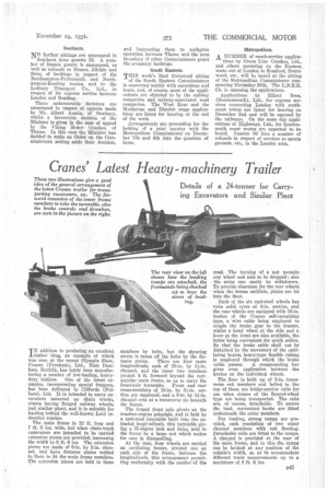
Cranes' Latest Heavy -machinery Trailer
Page 63
If you've noticed an error in this article please click here to report it so we can fix it.
Details of a 24-tonner for Carrymg Excavators and Similar Plant
IN addition to producing an excellent timber drag, an example of which was seen at the recent Olympia Show, Cranes (Dereham), Ltd., East Loreham, Norfolk, has lately been manufacturing a number of low-loading, heavy duty trailers. One of the latest examples, incorporating special features, has been delivered to Cliffords (Fulham), Ltd. It is intended to carry excavators mounted on chain tracks, cranes having flanged railway wheels, and similar plant, and it is suitable for hauling behind the well-known Latil industrial tractor.
The main frame is 12 ft. long and 7 ft. 6 ins, wide, but when chain-track excavators are intended to be carried extension pieces are provided, increasing the width to 8 ft. 6 ins. The extension pieces are made of 6-in. by 3-in, channel, and have distance plates welded to them to fit the main frame members. The extension pieces are held to these
members by bolts, but the shearing strain is taken off the bolts by the dis tance plates. There are four main longitudinals, each of 10-in. by 3i-in. channel, and the inner two members project 4 ft. forward beyond the rectangular main frame, so as to carry the front-axle turntable. Front and rear
cross-members of 10-in, by section are employed, and a 9-in. by 3i-in. channel acts as a transverse tie beneath the frame.
The forged front axle pivots on the traction-engine principle, and is held by a cast-steel turntable built into the extended longitudinals, this turntable giving a 35-degree lock and being held in the frame by a large nut which makes for ease in dismantling.
At the rear, four 'wheels are carried on oscillating beams, pivoted one on each side of the frame, between the longitudinals, this arrangement permitting conformity with the camber of the road. The turning of a nut permits any wheel and axle to be dropped ; also the axles can easily be withdrawn. To provide clearance for the rear wheels when the beams oscillate, plates are let into the floor.
Each of the six cast-steel wheels has twin solid tyres of 6-in. section, and the rear wheels are equipped with 16-in. brakes of the Cranes self-energizing type, a wire cable being employed to couple the brake gear to the tractor, whilst a hand wheel at the side and a lever at the front are also available, the latter being convenient for quick action. So that the brake cable shall not be disturbed by the movement of the oscillating beams, heavy-type flexible tubing is employed through which the brake cable passes. A compensating bar gives even application between the brakes on the individual wheels.
The floor is built up of 3-in, transverse oak members and bolted to the top of these are bridge-section rails for use when cranes of the flanged-wheel type are being transported. The rails are, of course, detachable. To secure the load, convenient hooks are fitted underneath the outer members.
For loading, strong ramps are provided, each consisting of two outer channel members with oak flooring. Detachable rails are fitted to the ramps. A channel is provided at the rear of the main frame, and to this the ramps can be hooked at any position of the vehicle's width, so as to accommodate different track measurements up to a maximum of 8 ft. 6 ins.