 1
1 2
2 3
3 4
4 5
5 6
6 7
7 8
8 9
9 10
10 11
11 12
12 13
13 14
14 15
15 16
16 17
17 18
18 19
19 20
20 21
21 22
22 23
23 24
24 25
25 26
26 27
27 28
28 29
29 30
30 31
31 32
32 33
33 34
34 35
35 36
36 37
37 38
38 39
39 40
40 41
41 42
42 43
43 44
44 45
45 46
46 47
47 48
48 49
49 50
50 51
51 52
52 53
53 54
54 55
55 56
56 57
57 58
58 59
59 60
60 61
61 62
62 63
63 64
64 65
65 66
66 67
67 68
68 69
69 70
70 71
71 72
72 73
73 74
74 75
75 76
76 77
77 78
78 79
79 80
80 81
81 82
82 83
83 84
84 85
85 86
86 87
87 88
88 89
89 90
90 91
91 92
92 93
93 94
94 95
95 96
96 97
97 98
98 99
99 100
100 101
101 102
102 103
103 104
104 105
105 106
106 107
107 108
108 109
109 110
110 111
111 112
112 113
113 114
114 115
115 116
116 117
117 118
118 119
119 120
120 121
121 122
122 123
123 124
124 125
125 126
126 127
127 128
128 129
129 130
130 131
131 132
132 133
133 134
134 135
135 136
136 A High-speed Industrial Truck
Page 94
If you've noticed an error in this article please click here to report it so we can fix it.
INDUSTRIAL trucks run at low speeds and are usually confined to off-theroad duties. This means that when required at a new site they have to be transported by lorry. Patent No: 771,676 (Electro-Hydraulics, Ltd., Liverpool Road, Warrington) shows a truck of this type fitted with an extra gearbox to enable it to reach reasonable road speeds and run under its own power to .1 new location.
The drawing shows a fork-lift truck though the scheme is not limited to such machines. The engine (1) carries the usual clutch (2) and a standard gearbox (3), this drives a transfer gearbox (4) which brings the .drive out at a lower level and gives the large reduction required when working.
All four wheels are driven, but the gearbox allows one axle to be disconnected at will. Transverse springing is used, whilst the steering gear is duplicated to allow the vehicle to be driven in either direction. Interlocks are provided to prevent the machine being driven at road speeds with two axles driven and the lifting fork in use.
EMPTY-SEAT INDICATOR
THE aim of a device shown in patent No. 769,562 is to indicate to the conductor of a double-decker the number of vacant seats.on the top deck. Operated by current from the vehicle battery, it indicates by lights the state at the upper deck load. (F. Miller, 114 Clough Lane, Burnley.)
AN MR-BRAKE VALVE
IN vehicles braked by compressed air 1 it is advantageous to have the ratio between the front and rear braking forces adjustable, particularly so when considering a tractor-trailer cornbina-lion. A valve in which the ratio can be instantly adjusted by the driver to 'suit the load is featured in patent No. 770,835. (Westinghouse Brake and Signal Co., Ltd., 82 York Way, London, NJ,)
The brake valve shown opens two air circuits, each controlled by a piston as indicated at 1. The pistons are operated by a push-rod 2, a rocking lever 3 and springs 4. The resistance of the springs controls the quantity of air passed and therefore the degree of braking.
The scheme for varying the ratio depends on modifying the force exerted by one spring; the righthand one is that chosen.
The action of the spring is modified by a lever (5). This is loaded by a spring (6) and pivots about pin 7, thus reducing the load on the spring of the piston, so that it opens earlier than the left-hand one.
The pivot pin is a movable part which can be slid along a ramp (8) by lever 9. The last is under the control of the driver who thus has an instant control over the braking proportionality.
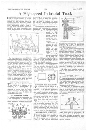
A DYNAMO-CUM-EXHAUSTER
(AN a vacuum-braked vehicle it is usual to provide some form of exhauster. To be small this would have to be a high-speed unit and it is not easy to find a convenient driving source To unite the exhauster with the dynamo and so take advantage of an existing high-speed drive is the aim of patent No. 771,595. (G. Rackham and Simms Motor Units Ltd.', Oak Lane, London. N.2.) The drawing shows the dynamo CO and the attached exhauster (2). The latter, is a vane-type pump and is a separate unit, being driven by •an Oldham coupling (3). The patent covers also the driving of an air compressor or an oil pump by the same means.
PRESSURE-WAVE INJECTION
THE initial spray from an injector I should desirably have a pressure in the region of 15,000 p.s.i., whereas the rest of the charge can be injected at 5,000 psi. An injection pump that provides this characteristic is disclosed in patent No. 771,326. (A. Evans and C. Hopkins, Parkside House, Wise Lane. Mill Hill, London, N.W.7.) The drawing shows a combined pump and injector, but one pump can be used to serve several injectors if required. On the downstroke, suction is created in a closed chamber (l) when a port (2) emerges from its sleeve, and fuel immediately enters. On the upstroke, the fuel is compressed in this chamber for about half stroke. there being no outlet whatever The high pressure thus created is released in the form of a sonic wave as soon as the discharge port (3). opens to the bore (4). The main fuel inlet is shown at 5, the aperture (6) being only for air-bleeding purposes.
The high initial pressure created is said to give optimum spray into the cylinder at the commencement of injection.
• A ROTARY VALVE
PATENT No. 771,137 shows a rotary valve working on a flat sealing face and provided with curved gas channels. The chief features are the means for cooling and for balancing the valve. (NSU Werke A.G., Neckarsulm/ Wurttemberg, Germany.)
The upper part of the valve is made from a steel casting, but the working ring (1) is of nitrided steel, brazed on to the casting. Balancing is achieved with recesses approximately opposite the gas channels.
. The hollow interior, forms a cooling jacket round which oil is circulated. A central tube (2) is the feed, the return path being through the annular space between it and a second tube (3). This outer tube also functions as the driving shaft of the valve.