 1
1 2
2 3
3 4
4 5
5 6
6 7
7 8
8 9
9 10
10 11
11 12
12 13
13 14
14 15
15 16
16 17
17 18
18 19
19 20
20 21
21 22
22 23
23 24
24 25
25 26
26 27
27 28
28 29
29 30
30 31
31 32
32 33
33 34
34 35
35 36
36 37
37 38
38 39
39 40
40 41
41 42
42 43
43 44
44 45
45 46
46 47
47 48
48 49
49 50
50 51
51 52
52 53
53 54
54 55
55 56
56 57
57 58
58 59
59 60
60 61
61 62
62 63
63 64
64 65
65 66
66 67
67 68
68 69
69 70
70 71
71 72
72 73
73 74
74 75
75 76
76 77
77 78
78 79
79 80
80 81
81 82
82 83
83 84
84 85
85 86
86 87
87 88
88 89
89 90
90 91
91 92
92 93
93 94
94 95
95 96
96 97
97 98
98 99
99 100
100 101
101 102
102 103
103 104
104 105
105 106
106 107
107 108
108 109
109 110
110 111
111 112
112 113
113 114
114 115
115 116
116 117
117 118
118 119
119 120
120 121
121 122
122 123
123 124
124 125
125 126
126 127
127 128
128 129
129 130
130 131
131 132
132 133
133 134
134 135
135 136
136 137
137 138
138 139
139 140
140 141
141 142
142 143
143 144
144 145
145 146
146 147
147 148
148 149
149 150
150 151
151 152
152 153
153 154
154 155
155 156
156 157
157 158
158 159
159 160
160 161
161 162
162 163
163 164
164 165
165 166
166 167
167 168
168 169
169 170
170 171
171 172
172 173
173 174
174 175
175 176
176 177
177 178
178 179
179 180
180 A VULCAN TWO-TON LIFTING VAN.
Page 88
Page 89
If you've noticed an error in this article please click here to report it so we can fix it.
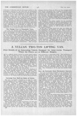
First Details of an Interesting Vehicle Designed for Inter-works Transport Where the Floors are at Different Heights.
IT is a difficult matter always to ensure equal heights in all the loading bays of a factory that has been extended from time to time, or where there is a number of associated depots or warehouses. In addition, docks, railway sidings, etc.; have to be negotiated, and in many cases the loading heights are beyond the control of any transport department. A Manchester cotton manufacturing concern—.fothergill and 1farvey, Ltd.—is working under such Conditions, and to meet the coutingenay . has ordered a special Vulcail van, the body of which can be raised or lowered by the driver easily, quickly andwith safety.
The vehicle chosen for the work is the standard 2ton Vulcan chassis, adapted to suit the special conditions for lifting the body, the lifting gear being installed direct on to the.framework. Before proceeding farther, it seems to be opportune to give a brief description of the duties which the vehicle has to perform.
Carrying Four Half-ton Bales of Cotton.
• The van is primarily intended to be used for trans-. . porting bales of cotton, complete with a " stillage," from factory to factory, each bale weighing approximately half a ton. Actually, a stillage is a wooden platform just large. enough to receive a half-ton bale of cotton. Iu . the ordinary way, the stillage, complete with cotton, is transported (for short distances only, of course) by hand-operated trucks which lift the stillage off the ground so that the truck supports the weight on its wheels. For inter-factory work., however, it will easily be seen that the transport could more easily be accomplished if several stiliages could be taken at once.It was decided that four should be carried, making a total load of about 2 tons, which necessitated the measurements for the body being 8 ft. 6 ins, length and 6 ft. width, whilst the headroom Of 6 ft. 6 ins, was so arranged that a man of ordinary stature could work easily without being cramped.
Before describing the hoist mechanism we will give a few details of the chassis. The engine is a foureylindered monobloc type, with cylinders of 95 mm. bore and a piston stroke of 130 mm., rated at 22.4 h.p. Side-by-side valves are houFed in the cylinder block
c30
and covered by a detachable head. The carburetter is a Zenith, bolted direct to the off side of the cylinder block. A fabric-faced cone clutch fitted With adjustable springs transmits the drive to a four-speed gearbox with central control. The ratios are: first gear 28 to 1, second gear 18.6 to 1, third gear 11.25 to 1, and fourth gear 7.25 to 1, The final drive is by overhead worm in a Kirkstall-pattern rear-axle casing. The foot brake is an external-contracting 'band acting on a drum behind • the gearbox, whilst the hand brake operates internal-expanding shoes in the rear drums -only. The wheelbase is 11 ft,,, and the overall length 17 ft.
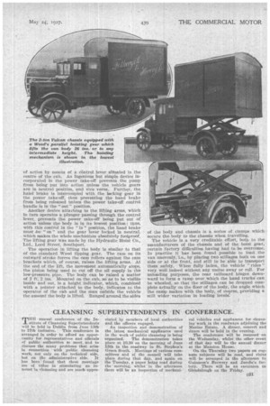
How the Hydraulic Hoist Mechanism Operates.
The hoist mechanism is similar to the standard Wood end-tipping gear, except that, in this particular arrangement of the gear, a parallel upward Motion is obtained by two pairs of crossed links. A single horizontal hydraulic cylinder (of cold-drawn steel tubing, incidentally) is carried longittiainally by means of angle members located across the chassis frame. This cylinder contains a piston fitted with two rings. Passing rearwards through a gland is a steel piston
• rod carrying a crosS-head and cross-arm on which are mounted steel rollers bearing on R.S.J. tracks, which are also bolted to angle members running across the chassis. A second pair of rollers on the cross-arm bears against a pair of cam 5rackets, the method of attachment departing from the usual Wood practice in that they are not attached to the body, but are bolted to a pair of channel-section lifting arms hinged at the rear or the chassis.
The front end of the lifting arms carry rollers which are free to roll in the body under-frame. A steel fulcrum pin on which is mounted another pair-of lifting arms (lifting the rear of the body), together with the first-mentioned pair of lifting arms, form a scissors structure having four fixed and four free ends. A standard Wood rotary pump carried in front Of the hydraulic cylinder is connected by steel tubing to the high and low-pressure ends of the cylinder„ The pump is driven by means of a. power take-off attached to the gearbox of the lorry, and is put " in " and " out " of action by means of a &intro' lever sitkuated in the centre of the cab. An Ingenious but simple device incorporated in the power take-off prevents the pump from being put into action unless the vehicle gears are in neutral position, and vice versa. Further, the hand brake is interconpled with the locking gear in the power take-off, thus preventing the baud brake from being released unless the power take-off control handle is in the "out" position.
Another device attaching to the lifting arms, which in turn operates a plunger passing through the control lever, prevents the power take-off being put out of action unless the body is in its lowest position; thus, with this control in the " in " position, the hand brake must be "on" and the gear lever locked in neutral, which makes the whole mechanism absolutely foolproof. The lifting gear was made by the Ilydraulic Hoist Co., Ltd., Lord Street, Southport.
The operation in lifting the body is similar to that of the standard Wood tipping gear. The ram on its outward stroke forces the cam rollers against the cam brackets which, of course, raises the lifting arms. At the end of the lift, the movement automatically stops, the piston being used to cut off the oil supply in the low-pressure pipe. The body can be raised a matter of 2 ft. 2 ins. Mounted on the cab, so as to be visible inside and out, is a height indicator, which, combined with a pointer attached to the body, indicates to the operator of the cab and the man oufside the vehicle the amount the body is lifted. Ranged around the sides
of the body and chassis is a series of clamps which secure the body to the chassis when travelling.
The vehicle is a very creditable effort, both to the manufacturers of the chassis and of the hoist gear, certain factory difficulties having had to be overcome. In practice it has been found possible to load the van unevenly, i.e., by placing two stillages both on one side. or at the front, and still to be able to transport them safely. When fully laden, the vehicle." rides" very well indeed without any undue sway or roll. For unloading purposes, the rear tailboard hinges downward to form a ramp over which the hand trucks can he wheeled, so that the stillages can be dropped complete actually on the floor of the body, the angle which the ramp makes with the body, of course, providing a still wider variation in loading levels: