


CHARGING ARRANGEMENTS FOR ELECTRICS.
Page 22
Page 23
Page 24
If you've noticed an error in this article please click here to report it so we can fix it.
The Best and Most Economical Method of Obtaining a Suitable Charging Voltage. The Size of Plant Required and the Necessary Switchboard Fitments.
By Chief Engineer.
THE WRITER recently described, with diagrams of an elementary nature, the' method of connecting up an electric aecumulatez battery for charging. Henow proposes to describe and illustrate the actual apparatus employed in practical work and to indicate its correct use for regulating voltage and current when charging the battery: The first essential is direct current of a voltage suitable for the battery to be charged. If the 'voltage of the source of supply is not correct, which is more than likely to be the case, a suitable voltage must he obtained by one of the following methods:
(1) Reducing voltage of supply by inserting a variable resistance.
(2) Installing a small generating set with dynamo arranged to give a correct voltage.
(3) Installing a, motor generator or rotary converter. .
The first method is wasteful and should only be employed where the voltage of the source of supply is only a little too high. The second method is very convenient in isolated situations not served by public supply mains. The third method is by far the most .' economical and simple, and should be employed where public power mains are available. Whether the , supply is direct or alternating current does not matter, as a machine can be installed that will convert and correct both current and voltage as desired. Having deoided upon the best ecr6nIe for obtain ,. ing a suitable charging voltaçe, the necessary apparatus must be installed.. This will consist of a generating plant, if any is required, a switchboard, ' and charging plug or plugs. The size of the generating plant will depend upon the number and size of the vehicles to be employed. This applies whether a motor ,generator, rotary converter, or separategenerating plant is installed. In order to arrive at the size of plant required, it. will be necessary to estimate the maximum charging current that will be needed. at any one time. Now, the size of machine necessary is denoted by the output in kilowatts, the kilowatt being the practical unit
employed by the manufacturers of electric generating machinery and is one thousand watts. A watt is one volt multiplied by one ampere, so that the maximum voltage of a machine, multiplied by the maximum current obtainable, and the result divided by 1,000, gives the maximum kilowatt output. Assume, for a Moment, that the prospective user of electrics expects to start with one ton vehicle, fitted with Ironclad Exide batteries, comprising 44 cells. He will have to arrange for a maximum voltage of 115 and for a normal maximum charging current of, say, 40 amperes. Therefore, the kilowatt output of the machine will be, 40 x 113 ÷ 1,000 =:.-44 kilowatts.'
This assume.sthat a boosting charge will not be required., but, if the vehicle is likely to run a greater
mileage on any one day and, consequently, requires more current than the battery is capable of supplying on a normal discharge, it will be necessary to give a boosting charge, that is, a charge of great intensity for a short period. The amount of current required for this will depend upon the time available and the condition of discharge of the battery. With the size of battery at the moment under consideration the maximum currant required for boosting may reach 160 amperes, so that the output in kilowatts may be 160 x 110 1,000 = 17.6 kilowatts, It will be noticed that, if a machine of this size is installed in the first instance, whether boosting is resorted to or not, the capacity is-such that three or four machines can be even a normal charge at one time. If it is likely that one single vehicle is the forerunner of a fleet, it will probably be most! economical to install the larger machine at once. The next item to be considered is the switchboard, which should have the following fitments to be complete:—
Voltmeter. Ammeter. Shunt resistance and rheostat. Reverse current switch.
Overload fuses.
Instrument fuses.
The voltmeter and ammeter, as their names indicate, enable the voltage and current intensity to be read. By means of the shunt resistance, the voltage can be adjusted until the correct charging current is passing through the battery. The reverse current switch is designed so that, should the voltage of the charging current by any chance fall below the battery voltage, it will open automatically, breaking the circuit and preventing the battery discharging through the generator, which itwould otherwise do. The fuses are required to protect the main circuit and the instruments respectively from a destructively high current.
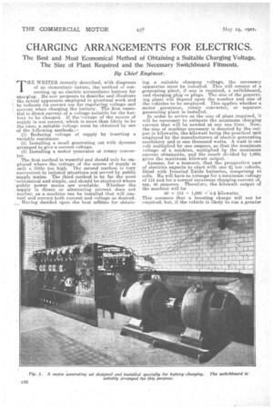
Fig. 1 is an illustration of a motor generating set built by the General Electric Co., Ltd., specially for battery charging. To the left of the photograph is seen the switchboard suitably arranged for charging.
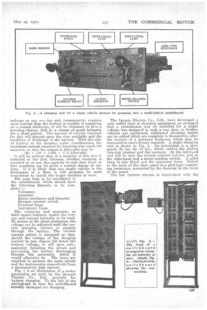
The Igranie Electric Co., Ltd., have developed a very useful form of charging equipment, so arranged that a switchboard may be installed for a single vehicle, but designed in such a way that, as further vehicles are purchased, additional charging panels can be added which are complete in themselves, after the manner of a sectional bookcase, which may be increased as one's library expands. A single charging unit is shown in Fig. 2. Its foundation is a slate panel, 24 ins. by 10 ins., which carries the sliding itecstat brushes and the contacts. At the left-hand end will be seen the reverse current eut,out, and at the right-hand end a meter-reading switch. A pilot lamp is also fitted and the necessary fuses. Belted to the back of the slate panel is.a grid-type regulating resistance, controlled by the rheostat on the front of the panel.
The low current cut-out is interlocked with the sliding rheostat brush crosshea.d in such a manner that it cannot be closed unless the rheostat is in the " all in" position. When the latter is in this position and the cut-out closed, a small magnet, placed in series with the charging circuit, holds it closed. Should the charging voltage, however, fall below that of the battery, the small electro-magnet lases its magnetism and the cutout opens. This will also happen should an interruption occur in the charging current. This ensures that the battery or batteries under charge cannot discharge into the circuit and, if more than one battery is, being charged, through each other. This, or a similar type of switch, should never be omitted.
The meter-reading switch at the right-hand end of the panel has three positions :— 1) Open.
2) Closed. (3) Meter reading.
When the switch is in the " open " position, no charging can be done, as the main circuit is interrupted and the battery is completely disconnected. When the 'switch is at the " closed" position, the circuit to the battery is completed and charging can proceed. When the switch is in the third position, the voltage and current of the battery under charge can be ascertained.
It will be noted that the panel does not contain a meter. These are separate items, because it is quite unnecessary to have more than one set, however many panels are required. Generally a duplex meter is provided, which indicates both volts and amperes and is fitted to a swing bracket on one side of the switchboard. This meter is connected to each panel, and by placing the switch on the " meter-reading " stop on any panel, the voltage and cuirent of that particular panel is indicated on the meter.
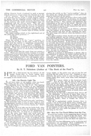
In Figs. 3 and t there are shown a front and a back view of a board arranged for charging six batteries at once. The duplex meter will be noted at the righthand side of Fig. 3. Fig. 4 shows, very distinctly, the connections at the rear -of the board. The two wide vertical strips are the bus bars, to which the mains are connected by means of the connecting lugs shown near the centre of the board.
The method of operating is as follows :—Assume that the battery to be charged is connected to one of the circuits and that all the switches are open. The pilot lamp will indicate when the battery is-connected up.
The meter-reading switch should now be moved to the reading position, and the battery voltage will he indicated if-the battery leads are properly connected ; if not, the needle of the instrument will be delleeted in the reverse direction. If the battery is connected up correctly, the reverse current cut-out switch should be closed and then the rheostat slidor moved to the left-hand until the charging current is adjusted to the amperage advised by the makers of the battery. It is not necessary to keep the switch to the reading position. It may be allowed to spring back so soon as a reading has•been obtained.
When it is desired to discontinue a charge, this is accomplished by placing the meter-reading switch at the " open" position, when the cut-out will automatically open and the battery will be completely disconnected. The charging plug can Shen be removed from the vehicle.: