


Steering, 9
Page 54
If you've noticed an error in this article please click here to report it so we can fix it.
BURMAN and Sons, a member of the Adwest Group, and a major manufacturer of steering boxes can trace its history back to 1873.
William Burman specialised in making horse clippers but many other widely different articles were produced.
For a short period a motorcycle engine was made and later a very popular motor-cycle gearbox was produced and sold in thousands. In 1930/31 arrangements were made for the company to manufacture a patented steering gear.
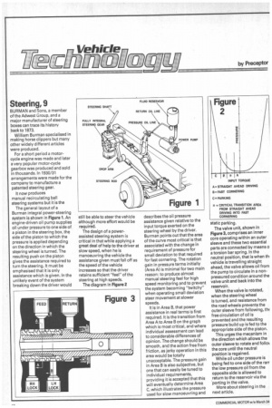
It now produces manual recirculating ball steering systems but it is the The general layout of a Burman integral power-steering system is shown in Figure 1. An engine-driven oil pump supplies oil under pressure to one side of a piston in the steering box, the side of the piston to which the pressure is applied depending on the direction in which the steering wheel is turned. The resulting push on the piston gives the assistance required to turn the steering. It must be emphasised that it is only assistance which is given. In the unlikely event of the system breaking down the driver would still be able to steer the vehicle although more effort would be required.
The design of a powerassisted steering system is critical in that while applying a great deal of help to the driver at slow speed, when he is manoeuvring the vehicle the assistance given must fall off as the speed of the vehicle increases so that the driver retains sufficient "feel" of the steering at high speeds.
The diagram in Figure 2 describes the oil pressure assistance given relative to the input torque exerted on the steering wheel by the driver. Burman points out that the area of the curve most critical is that associated with the change in requirement of pressure for small deviation to that required for fast cornering. The rotation gain in pressure terms initially (Area A) is minimal for two main reason: to produce almost manual steering feel for high speed monitoring and to prevent the system becoming "twitchy" when operating small deviation steer movement at slower speeds.
It is in Area B, that power assistance in real terms is first required. It is the transition from Area A to Area B on the graph which is most critical, and where individual assessment can lead to considerable differences of opinion. The change should be smooth, and the action free from friction, as jerky operation in this area would be totally unacceptable. The pressure gain in Area B is also subjective, but one that can easily be tuned to individual requirements, providing it is accepted that this will eventually determine Area C, which illustrates the pressure used for slow manoeuvring and static parking.
The valve unit, shown in Figure 3, comprises an inner core operating within an outer sleeve and these two essential parts are connected by means o a torsion bar spring. In the neutral position, that is when thi vehicle is travelling straight ahead, the valve allows oil from the pump to circulate in a nonpressured condition around the valve unit and back into the reservoir.
When the valve is rotated, when the steering wheel is turned, and resistance from the road wheels prevents the outer sleeve from following, thE free circulation of oil is prevented and the resulting pressure build up is fed to the appropriate side of the piston.
This urges the mecanism in the direction which allows the outer sleeve to rotate and folio the core until the neutral position is regained.
While oil under pressure is being fed to one side of the rarr the low pressure oil from the opposite side is allowed to return to the reservoir via the porting in the valve.
More about steering in the next article.