


Universal Spring Fixings
Page 90
If you've noticed an error in this article please click here to report it so we can fix it.
DATENT No. 859,360 refers to heavy 1 vehicles of the type having a short axle on each side, each of which carries a pair of wheels, and shows an improved means of attaching the leafsprings to the chassis. (Cranes (Dereham), Ltd., South Green Works, Dereham, Norfolk.) The drawing is a side view from between one pair of wheels. The axle is centrally clamped to the leaf-spring and the ends of the spring are held in split spherical sockets (1). The socket is made of metal; but the inside ball is of hard rubber, slotted to receive the end of the spring. Between the hard rubber ball and the socket is a layer of sofi rubber. This is resilient enough to accommodate the Movement of the spring in any direction.
Advantages claimed for the design• are cheapness of manufacture of the end fittings, reduced maintenance; and long life. There should also be freedom from rattles.
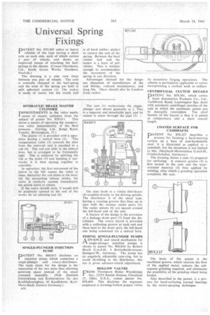
HYDRAULIC BRAKE MASTER CYLINDER IMPROVEMENTS in the valve mech1 anism of master cylinders form the
subject of patent No. 859,911. This shows a means of operating the recuperation valve independently of the fluid pressure. (Girling, Ltd., Kings Road, Tyseley, Birmingham, 11.) The piston (1) is provided with-a nose piece having a central bore (2). The recuperation valve (3). controls the inlet from the reservoir and is attached to a rod (4). The rod can slide in the central bore, but is arranged to be frictionally tight. This is achieved by splitting the rod at the point (5) and bending it outwards; it is then sprung together in assembly.
In operation, the first movement of the piston to the left causes the valve to close, thereafter the rod slides in the bore. On the succeeding release stroke, the valve is similarly opened immediately the piston starts to return.
If the valve should stick, it would still be positively opened at the end of the stroke by an 'abutting cap (6).
SINGLE-PLUNGER INJECTION PUMP
DATENT No. 860,015 discloses an
injection pump which comprises a single-plunger and rotary-distributor. The main claim for the design is the separation of the two units thus allowing generous space instead of the usual cramped assembly. (Veb Zentrale Entwicklung end Konstruktion far den Kraftfahrzeugbau, 45 Kauffahrtei, KarlMarx-Stadt, Eastern Germany.) 1356 The cam (1) reciprocates the single-plunger unit .shown generally at 2. This is a Separate and detachable part, and its output is taken through the pipe (3).
. The pipe leads to a rotary distributor (4) coupled directly to the driving spindle, The distributor is of thefl usual type, having a rotating 'groove that-lines up in turn with the .various outlet ports (5).. The outlet unions (6) are spaced around the left-hand end of the unit.
A feature of the design is the provision of a leakage drain port (7) from the distributor. The rotary barrel is provided with a collecting groove at each end and these lead to the drain port, the left-hand one being connected via a central bore.
TIMING SINGLE-PLUNGER PUMPS
ADVANCE and retard mechanism for single-plunger injection pumps is shown in patent No. 860,654 by Robert Bosch G.m.b.H., 4 Breitscheiderstrasse, Stuttgart-W., Germany. The pump has an angularly adjustable cam-ring, but to avoid throttling in the distributor, this too is given advance-retard adjustment.
HOLLOW VALVES
FROM Thompson Remo Wooldridge Inc., 23555 Euclid Avenue, Cleveland 17, Ohio, U.S.A., comes patent No. 859,469. This discloses the sequence employed in forming hollow poppet valves by successive forging operations. The scheme iS-partienlarly applicable to valves incorporating a coolant such as sodium CENTRIFUGAL CLUTCH DETAILS DATENT No. 859,501, which comes
from Automotive Products Co., Ltd., Tachbrook Road, Leamington Spa, deals with automatic centrifugal clutches of the type in which the automatic action can be manually, overridden. The chief feature of the layout is that it is aimed at compactness and a short overall length.
COATED SURFACE FOR CAMSHAFTS
PATENT No. 859,327 describes a process for forming' a had-wearing surface on a base of non-hardertable steel. it is illustrated as applied to a camshaft, but the invention is not limited to this. (Maybach-Motorenbau G.m.b.H.,
Friedrichshafen, Germany.)
The drawing shows a cam (I) prepared for surfacing. A concave groove (2) is first turned in the cam and the wearresistant material (3) then apPlied by welding, after which a grinding operation completes the cam.
The basis of the patent is the machined groove, which restricts the flow of the applied metal, reduces the subsequent grinding required, and eliminates the possibility of the grinding wheel being fouled.
Also described in the patent, is a process for hard-surfacing journal bearings by the metal-spraying technique.