


Suspensions which Relieve Frames from Strain
Page 64
If you've noticed an error in this article please click here to report it so we can fix it.
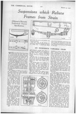
WHEN one looks along the average chassis from the rear while it is on uneven ground and without its body, it is hard to imagine how bodies can be made to withstand such distortion. It is, therefore, not surprising to see two prominent concerns making some effort to relieve the frame from such strains.
Patent No. 342,819, by G. A. Woodhead and T. H. Sanders, both of Leeds, describes a simple arrangement by means of which the weight bearing on the springs is balanced, so that, should one wheel be standing on high ground, its spring only bears its normal amount of weight. The springs are fixed at one end in the usual manner, to either dumbiron or bracket, and in the centre to the axle. The free ends of the springs bear against rollers attached to levers or arms extending from a rotatable cross-shaft. One spring is longer than the other, and the arms are also of uneven length, so that a perfect balance can be maintained.
Patent No. 342,855, by the Vulcan Motor and Engineering Co. (1906), Ltd., and S. A. Gregg, relates to a frame in which a second crosspiece is pivoted in the centre to the usual front cross-member, as shown on the left of the appropriate illustration.
The springs are attached at the front ends to shackles which are provided with spherical bearings to permit the springs to lengthen when loaded, and to roll side B46
AN infinitely variable gear shown in
patent No. 342,793, by A. Henderson, 12, King Edward Grove, Teeldington, and H. P. H. Anderson, 62, Eiger Avenue, ToIworth, Surrey, is very ingenious.
For the sake of clearness the shaft (F) can be left out -of the description, as it is only intended for use as a rightangle drive when such a drive is re quired.
The driving shaft is G, whilst B is the driven. Shaft G is connected to bevel wheel D1 and bevel pinion D. Two trunnions (l31) extend from B and on these the planetary pinions (C) rotate freely. Bevel wheel El runs freely on the driven shaft and carries with it bevel pinion E.
The two larger bevel wheels engage with pinions E2 and D2, D2 being mounted on the shaft Da, whilst E2 is attached to a sleeve which encloses the shaft. Owing to the fact that the two larger bevel wheels are of uneven diameter, it will be seen that if the bevel pinions (El and D2) be locked together so that they rotate at the same speed, the result will be that D1 will revolve with the driving shaft, being attached to it, and will carry with it the small bevel pinion (D). The larger wheel (El), owing to its engagement with the pinion (E2), would be revolving in a reverse direction to the driving shaft.
The effect of this would be that the trunnions (I31) would be carried in the same direction as the driving shaft, but at approximately half its speed, this being the highest ratio obtainable from this device.
We now come to the most interesting part of the scheme, viz., the means employed to differentiate the relative speeds of the pinions (El and D2). We have already shown that if these be locked together the highest speed is obtained, but if they were made to rotate in different directions at speeds proportional to the diameters of the-large bevel wheels, the trunnions and their shaft would remain still.
Shaft D3 terminates in a carrier for four pawls, whilst the sleeve of pinion E2 terminates in a cup-shaped member which has internal ratchet teeth. Another cup-shaped member (L) occupies the space between Da and the cup of E2, and carries on its Outer part four pawls. It also has internal teeth.
Mounted in a slidable bearing is L, which can move from a central position, as in Fig. 2, where D2 and E2 rotate as if locked together, to an eccentric position, as shown in Fig. 3. The pawls are so shaped that they can only engage with the ratchet teeth when the members are centrally situated or when they are extended as shown in the case of two of the pawls in Fig. 3. By this means the relative speeds of the pinions D and E can be varied awl the speed of the driven shaft controlled.