


Patents Completed.
Page 22
If you've noticed an error in this article please click here to report it so we can fix it.
Complete specifications of the following patents will be sent to any address in the United Kingdom upon receipt of eightpence per copy at the Sale Branch, Patent Office, Holborn, W.C.
SPARKING PLUG. — Bosch. — No. 30,049, dated under Convention 25th August, 1909.—This invention relates to sparking plugs having movable electrodes. In this type the armature under
goes a longitudinal movement in order to separate the electrodes, and so to extend the spark. The invention consists in the arrangement of a spring which serves to keep the electrodes normally in contact and which has to be overcome by the attraction of the armature at the moment of sparking. Between the core of the electro-magnet 'and the armature, is a pole piece which has a projecting pin formed with spiral grooves which accommodate one end of a spiral spring. The other end of this spring engages a similar spiral groove formed on the armature. This spring normally maintains the mov able electrode in contact with the stationary electrode.
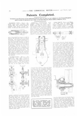
WATER-GAUGE. — M a a s. — No. 21,562-1909. dated under Convention 30th October, 1908.—This invention relates to a device for holding water-gauge glasses in position. The gauge glass is held in the lower cock in the usual manner, but, at the upper end, it bears
against a spherical projection formed 011 the lower member of a frame that surrounds the upper cock. The lower member of this frame is provided with a tubular extension that enters the stuffing box in the cock, so that it may be adjusted vertically to allow for slight differences in the length of the glass. This adjustment is effected by a screw secured to the head of the upper cock and engaging a nut formed in the frame member, the screw being provided with a suitable hand wheel. INTERNAL COMBUSTION E NGINES. — White and Another. — No. 25,302, dated 24th November, 1908.— This invention relates to internal-combustion engines of the well-known slidingsleeve-valve type, and has particular reference to that type in which a guide for the sleeve valves surrounds a water-jacketed working cylinder. The guide, in the present case, constitutes the outer wall of a water-jacketed cylinder, and is st!cured to the cylinder at that end which is remote horn the combustion chamber, thus nullifying the possibility of lateral spring or displacement thereof. The guide is extended up beyond the combustion chamber so as to lorm a water .jaeketed head, and the diameter of this head is such that the sleeve valves may be passed over it, thus allowing them Co be removed withoutdisplacing the cylinder. An outer casing is provided which encloses the sleeve valves. This casing is bolted to the head of the cylinder, and is also secured at the other end so as to avoid any possibility of its inner surface's getting out of centre with the outer surface of the valve-guide. The casing is so constructed and secured that it can he taken off, to enable the valves to be removed or inspected, without disturbance of the cylinder. The valveguide is formed with a boss which affords a junction for a circulating-water pipe, and it will be seen that, if this junction become damaged, it is prevented from delivering leakage water to the valves by the outer easing.
WORM DRIVE.—Brown and Others.
— No. 4,976, dated 1st March, 1909 (Patent of Addition to No. 7,054 of 1907).
— This invention relates to a wormdrive for motor vehicles, in which the driving wheels are mounted upon a dead
axle and are driven by electric motors— one carried on each side of the frame of the vehicle. The road wheel is carried by a sleeve that is mounted on the dead axle, and this sleeve also carries a wormwheel which gears with a worm carried by a shah that is mounted in suitable ball bearings arranged within a housing or easing. This casing surrounds and completely encloses the worm-gear, and is carried by a flanged sleeve that is free to oscillate on the dead shaft. The wormshaft is connected to a propeller shaft by means of a universal joint, and the propeller shaft is, in turn, connected to the motor by a universal joint, which also permits of slight movement of the shaft in an axial direction. The casing enclosing the gear is connected to the frame of the vehicle by means of a casing that encloses the propeller shaft. That end of this latter casing which is remote from the worm-gear has two studs which en
gage the forked arms of a bracket that is secured to the frame of the vehicle. This connection, while not permitting any vertical movement of the propeller-shaft casing, allows the casing enclosing the worm-gear to oscillate slightly upon the dead axle; thus in effect the casing enclosing the propeller shaft constitutes a torque rod which transmits the stresses to the frame of the vehicle.