


New Container I andling System
Page 48
Page 49
If you've noticed an error in this article please click here to report it so we can fix it.
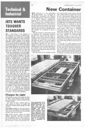
E prototype of a new side-loading FiI-container-transfer unit, developed by Silurfitt Bulk Transporters Ltd., Wisbech, was demonstrated last week in the presence Df a British Railways representative. Operated by one man, the base frame of a 20 ft. container with a simulated load of 6 tons was transferred from a road vehicle to the unit in under seven minutes. This was the first time that the exercise had been undertaken by one man and it is anticipated that it will normally be completed in about 5 minutes.
The unit is based on a semi-trailer and can be employed for transferring containers between road vehicles and rail wagons or between a lorry and the deck of a depot or warehouse. The mechanism of the transfer unit adds only about 7 cwt. to the weight of the trailer, which could readily be used for short-distance deliveries by road. It is envisaged by Murfitt that the unit would be ideal for depots where the high capital cost of an overhead crane would not be justified. The cost of a production transfer unit will be around £2,000.
The base frame of the container is fitted with special slotted corner sections and the base is drawn after the transfer unit with the aid of a roller-mounted sliding hollow bar at each end and two detachable pick-up blocks, which are also employed to push the container off the trailer on to another vehicle or loading deck. Four independently operated hydraulic jacks are employed to raise the level of the trailer to an appropriate height.
Power is provided by a 9 h.p. auxiliary petrol engine, which drives a Telehoist swashpiate pump connected to an Orbit rotary-type hydraulic motor. This can be reversed by changing the direction of fluid flow and operates two drum-and-cable mechanisms through a worm drive. Two pulley systems are used to relay movement of the cables to the sliding bars, the two ends of each cable being attached to the bar near its centre.
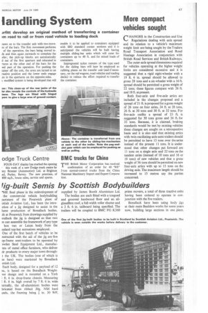
At the start of a loading operation the two pick-up blocks are placed in apertures in the sliding bars on the loading side of the vehicle and at the same time pegs on the blocks are inserted in slots of the container corner sections. The hook ends of a pivoted arm, incorporated in each block, engage a stop at the upper end and a ledge of the bar aperture at the lower end, and the container
rawn on to the transfer unit with two moveits of the bars. The first movement performs of the operation, the bars being moved inds and then again outwards to complete the sfer; the pick-up blocks are automatically d out of the first aperture and relocated in lures at the other end of the bars for the ind part of the operation. For pushing the tamer off the unit, the arms are turned to an rnative position and the lower ends engage es in the apertures on the opposite sides. modified system is being developed that will enable it to be applied to containers equipped with ISO standard corner sections and it is anticipated the vehicles will be built having multiple sliding-bar units which will cater for containers up to 40 ft. and for mixed loads of containers.
Impregnated nylon runners of the type used for the sliding bars will later be employed as rubbing plates on the transfer unit (and itneces sary, on the rail wagons, road vehicles and loading decks) to reduce the effort required to transfer the container.