


Two-chamber Tyre Tube With Double Valve
Page 36
If you've noticed an error in this article please click here to report it so we can fix it.
A Risurne of Patent Specifications that Have Recently Beeta Published
AN inner tube that gives the tyre
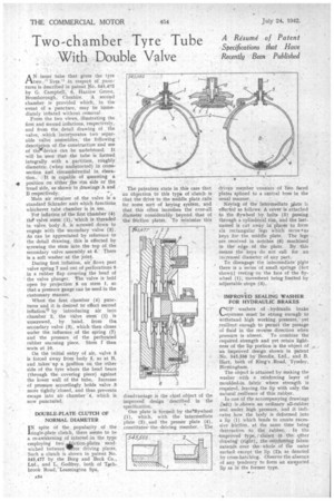
two " lives in respect of pinetures is described in patent No. 545,492 by G. Campbell, 6, 'Harrow Grove, Bromborough, Cheshire. A second chamber is provided which, , in the event of a puncture, may be immediately inflated without removal From the two views, illustrating the first and second inflations, respectively, and from the, detail drawing of the valve, which incorporates two separable valve assemblies, the following description of the construction and use of the device can be understood. It will be seen that the tube is formed integrally with a partition, roughly diametric (when undistorted) in crosssection and circumferential in eleva
tion. It is capable of assuming a ip position on either•ithe rim side or the tread side, as shown in drawings A and B respectively.
Main air retainer of the valve is a standard Schrader unit which functions whichever tube chamber is in use.
For inflation of the first Chamber (4) the valve stem (1), which is threaded in valve body 5, is screwed down to engage with the secondary valve (3). As can be appreciated by reference to the detail drawing, this is effected by s,crewing the stem into the top of the secondary valve assembly at 6. There is a soft washer at the joint.
During first inflation, air flows past valve spring 7 and out of perforations 9 in a rubber flap covering the head of the valve plunger. The valve is held open by projection 8 on stem 1, so that a pressure gauge can be used in the customary manner.
When' the first chamber (4) punctures and it is desired toeffect second inflation* by introducing air into chamber 2, the valve stem (1) is unscrewed, by hand, from the secondary valve (3), which then closes under the influence of the spring (7) and the pressure of the perforated rubber encasing piece. Stem f then seats at 10.
On the initial entry of air, valve 3
• is forced away from body 5, as at B, and takes' up a ppsition on the other side of the tyre where the head bears (through the covering piece) against the lower wall of the tube. Increase of pressure accordingly holds valve 3 more tightly-closed, and thus prevents escape into air chamber 4, which is, now punctured.
DOUBLE-PLATE CLUTCH OF NORMAL DIAMETER
IN spite of the popularity of the single-plate clutch, there seems to be a re-awakening of interesi.in the type employing two iiiiction-plates sandwiched between111.Free driving. plates. Such a clutch is shown in patent No. 545,477 by the Borg and Beck Co., Ltd., and L. Godfrey, both of Tachbrook Road, Leamington Spa.
The patentees state in this case that an objection to this type of clutch is that the drive to the middle plate calls for some sort of keying system, and that this often increises the over-all diameter considerably beyond that of the friction plates. To minimize this disadvantage is the chief object of the improved design described in the specification.
One plate is formed by the`flywheel 1), which, with the intermediate plate (2) and the presser plate (4), constitutes the driving member. The driven member 'consists of two faced plates splined to a central boss in the usual manner.
Keying of the intermediate 4ate i3 effected as follows: A cover is attached to the flywheel by bolts (5) passing through a cylindrical rim, and the lastnamed is cut away in places to form six rectangular legs which serve • as keys for the middle plate. The legs are received in notches (6) machined in the' edge of the plate. By this means the keys do not call for an increased diameter of any part.
To disengage the intermediate plate there is a series of small springs {not shown) resting on the face of the flywheel (1), movement being limited by adjustable stops (3).
IMPROVED SEALING WASHER FOR HYDRAULIC BRAKES
CUP washers of :hydraulic brake systems must be strong enough to withstand high working pressure,' yet resilient enough to permit the passage of fluid in the reverse direction when pressure is absent. To combine the required strength and yet retain lightness of the lip portion is the object of an improved design shown in patent No. 545,556 by Bendix, Ltd., and B. Hart, both of King's Road, Tyseley, Birmingham.
The object is attained by making the washer with a reinforcing layer of moulded-in fabric where strength is required, leaving .the lip with only the natural resilience of thin rubber.
In one of the accompanying drawings (left) is .shown an ordinary all-rubber seal under high 'pressure, and it indicates how the body is deformed into a lip (1) which tends to create excessive friction, at the same time being destructive to the rubber. In the .-.Improved type, shown in the other drawing (right), the reinforcing fabric extends over the, whole of the outer surface except the lip (2)a as denoted by cross-hatching. Observe the absence of any endency to form an unwanted lip as in the former type.