


COACH AND BUS BODY: N BALLS AND SPRINGS.
Page 18
Page 19
If you've noticed an error in this article please click here to report it so we can fix it.
The Unsatisfactory-Springing of Dual-purpose I ' the Body on the Chassis. Cush
A Problem Facing the Coachbuilder. Springing Means of Steel Balls and Cups.
WEHAVE, on Many occasion's, Commented upon . the tact that the springing of some of the .. commercial chassis enaplOyed for passenger work is not by any means so satisfactory as is desirable*. There aPpears. to he too great a tendency to build chassis which will meet the requirements bah of users who wish to employ their vehicles for the transport of merchandise and others who desire to use them„ n either as open coaches or buses, solely for the Carrying of passengers.
The resultof utilizing the ordinary forms of springing on passenger conveyances is to bring the bodybuilder face to ' face with a very awkward problem—that is, of fitting a comparatively rigid body to a chassis frame which may flex to a considerable extent under the effects-of load and uneven road' surfaces.
For ordinary lorry purposes the chaSiiS,frame may be sufficiently rigid,,but when the average coach or bus body is considered, it will at once be seen that any uneven stressing of these bodies will certainly have a most deleterious effect, which shows itself-in practice by an increasing teidericy for looseness and
cansequeht rattle to develop. . , . The Impracticability of the Rigid Frame.
As it is almost imPossible—at least, it appears to he so at the present juncture—to build a chassis • fi'ame which will be, for all'practical purposes, rigid, witheut being eicessiVely, heavy, it would seem that • we must look to some other means for isolating the bodies from abnormal stress and racking.
Efforts have already been made, and have been referred to by us in previous articles, to introduce cushioning devices between the body and chassis. in one instance which we recall to mind, efforts were made to utilize spiral springs for this' purpose' but not with any great Measure of success, although this• might have.been achieved if sufficient encouragement had been given to the inventor. There: are, :et course, many difficulties to be faced, The obvious one is that of the body, rolling which. might occur:Then them is:the question of the controls and as to whether these should be attached to the body or to the' chasSis ; again, there Would be slight movement between the .dashboard, which usually forms part -of the chassis, and the body. Naturally, the movement permitted need only be
slight ; in fact, just sufficient to damp out those lesser vibrations which are not effectually arrested by the main springs of a. chassis and to prevent excessive torsional or bending movements of the frame being conveyed to the body, Clever designers have been at work on the problem for some considerable time, and already two shock
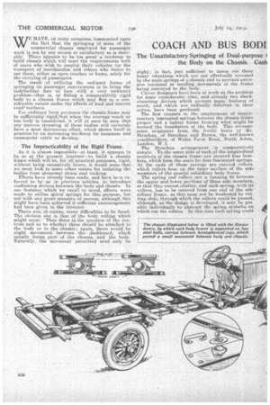
absorbing devices whidh present many, features of merit, and which are radically different in their action, have been produced. The first consists in the employment of supplementary laminated springs between the chassis frame proper and a lighter frame forming. what might he termed the: foundation of the body. This arrangement originates from the fertile brain of Mr.
• Strachan Strachan and Brown, the well-known coachlatilders, of Wales Farm Boad, North Acton, London, The Stra,chan arrangement is comparatively simple. To the outer side of each of the longitudinal members of the chassis frame are secured four brae' kets, which form the seats for four laminated springs. At the ends of these springs are carried rollers, which rollers bear on the inner surface of the side members of the special subsidiary body frame.
• The spring end rollers are a running fit between the upper and lower portions of these side Members, so that they cannot chatter, and each spring, with its rollers, has to be entered from one end of the subsidiary frame, as this must not he weakened, by cutting slots, through which the rollers could be Passed, although, as the design is developed, it may be possible individually to abstract the spring eyebolts -on which run the rollers. In this case each spring could
be dropped separately, and the rollers removed without any trouble.
• Each spring is provided with a centre bolt passing through the subsidiary frame members and provided at its upper end with bufferor cushion springs which preventundue rebound. These _bolts also prevent • the body from moving longitudinally, and sieatly
assist in damping out any tendency to roll.
It will be seen that the whole body is thus carried on eight spring S and rollers, giving very free action,
whilst the springs. thernSelyes, being comparativelyflexible, are of great assistance in reducing shock.
The invention is only now in course of develop• meat, and it remains to be seen how it works in prac
tice. Others of Mr. Strachan's inventions have achieved well-meritedsuccess, and we shall await with great interest the results of the tests with this new device • In order to assist our readers thoroughly to understand this new method of body springing, we publish drawings showing ad imaginary coach fitted with the device, and details of one of the springs.
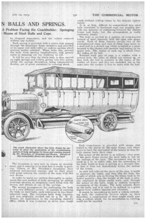
The second arrangement for cushioning the body is of a very different nature. It consists of carrying the body on steel balls, each contained in two hemi-sphericalcups. The invention hails from America, and was originally worked ou't by a Dr. W. D. Harper, for application to his travelling dentist's office, which it was necessary to drive over rough
roads 'without risking injury to his delicate instruments. .
It is, at first, difficult to comprehend how steel. balls contained in hardened cups can possibly provide any measure Of cushioning between the C.,hassis frame and body,i but the arrangement is really extremely simple. .
The body is carried by a number of cross-bearers formed of steel chimnels, with the open side downwards. Each of these bearers carries two of the hemispherical cups; and each of these cups bears on a steel ball in a second cup which is bolted to a plate secured to the chassis side member and resting on its upper web. The radius of each cup is about twice the radius of its ball.
Between each pair of cups is a washer with a central hole,the sides of which are turned up, so that with the ball in position in the centre of the washer all water and dirt are excluded, but at the same time the washer is free to move with the bail.
Each cross-bearer is provided with straps also boltedto the plates on the main frame, and which serve to limit the movement of the bearer so that the balls cannot leave their cups.
The action of the device is as follows:—Any sway of the main frame causes the steel balls to roll up the inclines of the cups. The movement may be as mtch.as in. to eithee side, but the momentum of the body tends to keep it moving in a straight line, so that it does not immediately follow the motion of the frame.
As eich hall rolls upthe curve of the cups, it tends to separate the latter, and thus lifts the body, -the weight of which acts iii forcingthe frame back to its former position; thus the weight of the body is actually employed in doing useful -work, and, through the action of the balls, tends to cushion irregular movements of the frames The body actually floats on the balls, and it is ca-id to be isolated ina great degree from sudden impacts and vibration.
it would be interesting to build a vehicle embodying both the etishioning devices which we have described, a combination of them might easily provide a vehicle which, for its smoothness in running, could not be excelled. • •