


A Radiator with Easily Removable Tubes
Page 78
If you've noticed an error in this article please click here to report it so we can fix it.
A Rdsume of Recently Published Patent Specifications
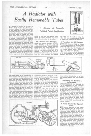
INpatent No. 341,421, H. Whitby, of Glyn Road, Ponders End, Enfield, describes a radiator in which any number of the tubes can be removed and replaced by others in a few minutes. The specification points out that radiators have been made in which the tubes were fitted with rubber washers, or sleeves, in compression for the purpose of making a water-tight joint between them and the perforated plates, but that in some previous constructions difficulty has been experienced in removing tubes that may have been damaged, owing to the heat, especially at the upper end, causing the rubber to vulcanize to the metal of the tube. Should this 'occur, it would not be easy to compress the sleeve by raising the tube sufficiently to release the lower end from its plate.
The main feature of the present taro tion appears to lie in the fact that the upper sleeve is so formed that it makes contact with the tube for only a certain distance, leaving sufficient of the sleeve free from any possibility of vulcanization, to enable the tube to be raised in order to free the lower end.
Metal washers are soldered to the tubes to form abutments for the rubber. In both upper and lower plates a groove is formed around the hole, in which the end of the rubber fits so as to keep it from contact with the tube.
The specification says that both upper and lower tanks may be cast integral with the portion that is to be perforated, thus dispensing with the separate perforated plate and its multiplicity of bolts and consequent risks of leakage. Owing to the long, free sleeves, there should be ample provision for expansion and contraction of the tubes.
An Unusual Road Sweeper.
THE road sweeper described in patent No. 341,762, by R. Diederieh, 27, Gumbendorferstrasse, Vienna, contains several novel and useful features, and should be of value where large quantities of road dust or mud have to be removed. As will be seen from the accompanying illustrations, it takes the form of a trailer equipped with a sepa rate engine which can drive the brushes at any speed irrespective of the forward speed of the prime mover.
It is also provided with separate steering, so that it can to some extent be steered on its own course instead of following in the wake of the tractor. By this means it can reach the gutter and can miss any obstacle that may be in its way.
The long roller (2) drives the dust to the path of the roller (5) which causes it to rise up the elevator and be discharged into the tractor. When the tractor is full it can be driven to the dump and another can take its place, so that the sweeping machine can remain at work all the time. The screw
jack (12) can be used to bring the roller (11) into contact with the ground to enable the tractor to be removed.
A Vaporizer for Oil Engines.
CERTAIN features which he claims to be improvements in engines provided with carburetters and using heavy oil are described by W. Wheeler, of 148, South Elliott Place, Brooklyn, U.S.A., in patent No. 341,131.
The main features of the invention lie in the formation of the combustion chamber, the position of the sparking plug, and the introduction of an e ectric heating element near the sparking plug.
Converting the Ford to a Six-wheeler.
SPECIFICATION No. 341,546, by L. D. Henderson, 13, Rue Dinocrate Mazarita, Alexandria, Egypt, describes an attachment which transforms a Ford 30-cwt. lorry into a six-wheeler capable of carrying a much greater load, without adding to the stresses sustained by the component parts of the chassis. This is done by adding girders to the side frames, using extra leaves in the springs, and forming a bogie almost entirely of parts to be obtained from the company which manufactured the original chassis.
A Farm Tractor for Special Work.
THE tractor described in the patent (No. 341,641) of J. H. McCollough, 20, West Santa Clara Street, San Jose, California, would appear to have been designed for special farm work, such as cultivating between the rows of crops.
The larger wheel is mounted on a hollow non-rotating axle to which the engine and its appurtenances are fixed, the smaller wheel being driven by means of a shaft and bevel gears. The steering is said to be so arranged that the machine can be easily turned in confined spaces. The controls to the engine are by meann of cables. •