


Control Valve for Hydraulic Braking
Page 36
If you've noticed an error in this article please click here to report it so we can fix it.
A R6urnz_ of Recently Published Patent Specifications E-ROM Fodens, Ltd., W. Foden and
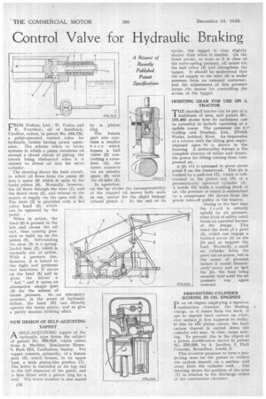
E. Twemlow, all of Sandbach, Cheshire, comes, in patent No. 556,725, a pedal-operated control valve for hydraulic brakes having power assistance. The scheme refers to brake systems in which a pump circulates oil around a closed circuit of piping, the circuit being obstructed when it is desired to divert oil into the servo cylinder.
The drawing shows the fluid circuit, in which oil flows from the pump (6) into a space (8) which is open to the brake piston (9). Normally, however, the oil flows through the bore (1), and the fluted stem (2), and returns to the source of supply via the open end (4). The stem (2) is piovided with a flat valve head (5), which can be operated by the pedal.
When in action, the head (5) is pressed to the left and closes the oil exit, thus causing pressure to build up on the piston (9). Surrounding the stem (2) is a springloaded liner (7), which is normally out of action. With a pressure rise, however, it is forced to the right and performs' two functions; it reacts on the head (5) arid so gives the driver a " feel," and it opens an alternative escape port, (3) for the release of excess pressure. As an emergency measure, in the event of hydraulic failure, the head (5) can 'directly operate the brake piston, and so give a purely manual braking effect.
NEW DESIGN OF SELF-ADJUSTING TAPPET
ASELF-ADJUSTING tappet of the hydraulic type forms the subject of patent No. 556,610, which comes from A. Buckley, Dorchester House, 9, Park Hill, Carshalton, 'Surrey. The tappet consists, primarily, of a female part (3) which houses, in its upper bore, a male pistonslike portion (1). The latter is extended at its top end to the full-diameterof the guide, and is here fitted with a piston ring for a seal. The lower member is also sealed
by a piston ring.
The female part also contains a smaller bore which houses a ball valve .(2) controlling a crossbore (4); the latter connects via an annular space (6) with the oil inlet (5).
In operation, • on the up stroke the incompressibility of the trapped oil moves both units as one, except for the slight leakage arOund piston 1. At the end of its stroke, the tappet is thus slightly shorter than when it started. On the down stroke, so soon as it is clear of the valve-spring pressure, oil enters via the bail valve (2) and relengthens the tappet. It should be understood that the oil supply to the inlet (5) is under pressure from an external container, and the adjustment of this pressure forms the means for controlling the action of the tappet.
HOISTING GEAR FOR USE ON A TRACTOR
THE standard tractor can be Put to a 1 multitude of Uses, and patent No. 356,466 shows how its usefulness can be extended to include operating as a mobile crane. The patentees are Goldnp and Stanhay, Ltd., Elwick Works, Ashford, Kent, An impression of a tractor witlethe lifting gear superimposed upon it is shown in the drawing. A noteworthy feature is the complete absence of cables and drams, the power for lifting coming from compressed air.
A jib (1) is arranged to pivot about
point 9 on the framework. This jib is . worked by a pull-rod (7), which is hell
cranked to the piston rod (8) of a pneumatically operated cylinder (5) A bottle (6) holds a working stock of air, the pressure of which is maintained by a compressor (4) driven from the power take-off pulley of the tractor.
Owing to the fact that the 1 o ad is entirely upheld by air pressure, some form of safety catch forms an essential feature of the design. This takes the form of a pawl (3), which can engage a toothed sector (2) on the jib and so support the load. Normally, a small air cylinder holds the pawl out of action, but in the event • of pressure failure it would immediately-move and so lock the jib, the load being securely held until the air pressure was again restored.
PREVENTING CYLINDER SCORING IN OIL ENGINES
I N an oil engine employing a separate combustion chamber, the flaming a charge, as it issues from the neck, is apt to deposit hard carbon on whatever surface it first happens to strike. If this be the piston crown, the hard carbon deposit is carried down the cylinder and May, in tithe, cause scoring. To prevent this is the object of a piston modification shown in patent No. 556,666, by A. Sanders, 1, Park Crescent, Roundhay, LeedS, 8.
This inventor proposes to form a projecting nose on the piston. to receive the carbon deposit on .a surface well away from the cylinder wall. The drawing shows the position of the nose (1.) in relation to the discharge orifice of the combustion chamber.