


A Specialized Tipper from Standard Units
Page 21
If you've noticed an error in this article please click here to report it so we can fix it.
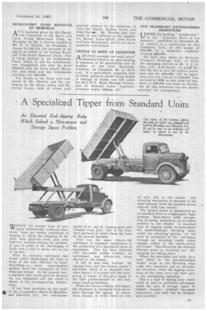
An Elevated End-tipping Body Which Solved a Man-power and Storage Space Problem WHILST the normal type of endtipper undoubtedly conserves manhours, there are certain conditions of tipping in which the dumping of . the load, from platforin level, goes only half-way towards solving the problem. A case. in point i8 the discharging of loads over a wall or stack, one-on top of another.
With an ordinary end-tipper this would entail discharging the load in front of the wall, followed by hand shovelling—a . most uneconomical method from the standpoint of both time, and labour. In the present case, a machine that would give an elevated tip was demanded and the result is shown in the 'accompanying illustrations.
It has been produced as the result of the co-operative efforts of Bromilow vr. and Edwards, Ltd., the well-known
maker of B. and E. tipping gears and Comrner Cars, Ltd., one of the standard products of which forms the basis of the present machine.
This was the main object—the, utilization of standard components in the production of a specialized piece of equipment. This has been achieved, with successful results without, we understand, any alterations being effected in the chassis,
It will be seen that, between the tipping body and the chassis, comes a sub-frame which is so mounted' that, when desired, it is raised with the body, giving a. degree of elevation equal to the limit predetermined by the lazytongs coupling members.
• When used as an ordinary end-tipper, the sub-frame is restrained from movement through the agency of screwdown clamps, of which there are two on'.. each side of the chassis. The elevating mechanism is operated in the usual manner, from the standard power .,.. • take-off, with cab control.
The motive power is transmitted by an auxiliary drive to a high-speed, highpressure, three-throw solid plungerram oil pump, situated in an accessible position in the chassis. A standard type of tipping cradle accommodates the multi-telescopic elevating rams, whilst the elevating portion of the rams is connected to the sub-frame through an elevating cradle which engages rollers in the rolled-section sub-frame. This allows for the different fulcrum point as elevating and discharging are taking place.
When the sub-frame and body have been lifted to the pre-determined height, stops in the elevating rams come into operation and so maintain the elevation, whilst the tipping extensions of, the rams carry out their part in the end-tipping operation.
This is a type of tipping body which could be used to particular advantage where the area of storage space is limited because, • without increased man-power, one load can be dumped upon another.