


Meeting Belfast's Special Conditions
Page 8
Page 9
If you've noticed an error in this article please click here to report it so we can fix it.
in Trolleybus Manufacture
UST over a year ago
Belfast Corporation Tramways Committee appointed a deputation to visit various centres in England where trolleybus systems were operating, with a view to considering the suitability of the type for Belfast.
It visited London, Wolverhampton, Birmingham, Bournemouth, Portsmouth and Nottingham, conferred with the municipal transport authorities and inspected the systems under their control. It also visited the works of a number of the principal trolley.; bus manufacturers and examined the several types of chassis available . for double-deck trolleybuses having bodies of large seating capacity.
As a result, it was decided to operate in Belfast for twelve months an experimental service of trolleybuses. Various makers were invited to supply vehicles for this service, so that data relating 4.20 to the individual makes would be obtained concurrently with the data applying to the working of a trolley bus system.
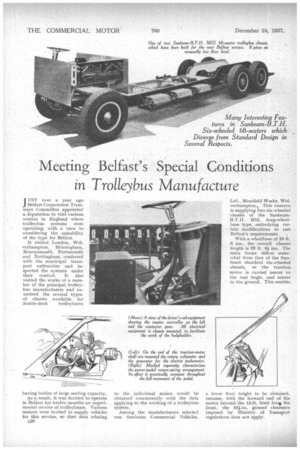
Among the marrufacturers selected was Sunbeam Commercial Vehicles, Ltd., Moorfield Works, Wolverhampton., This concern is supplying two six-wheeled chassis of the SunbeamB.T.H. MS2, long-wheelbase type, ernbodying certain modifications to suit Belfast's -requirements.
With a wheelbase of 18 ft. 6 ins., the overall chassis length is 29 ft. 4 ins. The main frame differs somewhat from that of the Sunbeam standard six-wheeled chassis, as the traction motor is carried nearer to the rear bogie, and nearer to the ground. This enables a lower floor height to be obtained, because, with the forward end of the motor beyond the 13-ft. limit fru.* the front, the 10-i-in. ground clearance imposed by Ministry of Transport regrilations does not apply. Actually, the lowest point of the motor, in its altered position, is 7/ ins. from the ground. With this arrangement the Sunbeam diagonal centre bracing of the frame could not be employed, but the necessary torsional rigidity has been secured by using extremely deep channel-section pressed steelcross-members.
Where the side members are most heavily loaded they are 11 ins, deep, and are extended to. 1'5/ ins, between the two rear axles, to carry the rearspring pivot-bearing brackets. Varying in width according to stress requirements, the flanges have a maximum width of 41 ins. There are stout tubular cross-members at the front and rear ends, making an exceptionally strong and rigid assembly.
Short Transmission Line.
The rearward position of the motor enables a short propeller shaft to be used for transmitting the drive to the middle axle, with a similar short shaft to the rearmost axle. These have Hardy Spicer needle-roller joints. A third differential is mounted on the middle axle.
From the motor to the axles the drive is practically straight, the maximum degree of angularity under normal road conditions being limited to 3°. Of hardened and ground steel, the worms mesh with phosphor-bronze wheels carried on roller bearings, the ratio being 9.33 to 1.
Mechanical and electrical braking is employed, the former being the Sunbeam-Lockheed hydraulic system. Of l in, diameter, the wheel cylinders are mounted on the outside of the brake-shoe carrier brackets on all three axles. A Dewandre vacuum-servo motor is included between the pedal and the master cylinder. Vacuum is provided by a rotary exhauster, driven from the forward end of the tractiou motor and effectively silenced by an expansion chamber.
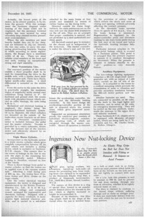
Triple Master Cylinder.
Incorporated in the hydraulic system is a triple master cylinder which gives complete compensation between all six. road wheels and includes a sealing device which is exclusive to SunbeamB.T.H. chassis. This ensures that in the event of leakage in the line to any axle the pipes to the remaining two are automatically sealed. Effective braking is, therefore, retained on four of the wheels.
There is direct linkage from pedal to master cylinder, so that the brakes can be applied even if the vacuum system fails. Affording a total facing area of 803 sq. ins., the brakes have 17-in. front drums and 20-in, drums on the bogie wheels.
Like the entire electrical traction equipment, the motor is designed and manufactured by the British Thomson. Houston Co., Ltd. It is of 95 h.p. (one hour rating) and compound wound, arranged for regenerative and rheostatic braking. Designed with a capacity for heavy overloads, it incorporates light material wherever possible, and is 'carried in a sub-frame attached to the main frame at four points and insulated by means of rubber bushes on the fixing bolts, Mounted outside the frame longitudinals, the main, resistances are on the near side and the shunt field resistances on the off side. They are so arranged that proper ventilation is ensured, and are protected by a steel undershield and stcine guard.
All electrical 'control gear is mounted on the chassis and is independent of the bodywork. The master controller is under the driver's seat and the unit houses the accelerating controller, the reverser and the rheostatic braking controller'. In this latest design the accelerating-controller portion of the unit is mounted above the reverse drum, which gives improved accessibility.
Supported on permanent aluminium panels the contactor, gear consists of individual electro-magnetic switches, the operating coils of which are energized threugh the master Controller. Silence of operation is obtained by the provision of rubber buffers which absorb the shock and noise of closing and opening, without, adversely affecting the contact pressure.
As the rheostatic brake operates down to speeds of 3-4 m.p.h., wear cin the brake facings is minimized. Regeneration is regulated by the master-controller pedal and rheostatic braking by the main brake pedal during the first part of its travel and before the hydraulic braking becomes fully effective.
Particular interest attaches to the power-pedal linkage which is covered by a Sunbeam patent, This pedal is so arranged that the pressure required to operate it is constant throughout its movement. When the pressure is released it returns smartly to the " off " position—a very desirable feature.
Auxiliary. Equipment.
The low-voltage lighting equipment comprises a 30-volt single-shaft motorgenerator set, with an output of 1,400 watts, carried on the off side of the chassis. It is attached to the frame by a resilient mounting which prevents the transmission of noise or vibration and provides secondary insulation between the 500-volt motor portion and the frame..
Alkaline batteries are used. They are connected in parallel, at 30 volts, for the feeds to the legal lights and accessories, and in' series, at 60 volts, for emergency manteuvring. They will be carried on the rear platform, underneath the staircase to the upper deck, and suitably enclosed.
These Sunbeam-B.T.H. chassis are to be equipped with 68-seater all-rne.tal bodies, which are being built by F..D. Cowieson and Co., 80, Charles Street, St. Rollox, Glasgow.