


Two-stage Cartridge Engine Starting
Page 26
If you've noticed an error in this article please click here to report it so we can fix it.
I N our issue dated July 30, 1937, we described a patent by Robert Bosch A.G., of Stuttgart, Germany, dealing with a method of starting large oil engines by a combination of electric motor and explosive cartridge.. The same concern now discloses, in patent No. 475,128 an improved scheme from which the electric motor is absent. The patentee states that the use of cartridges imposes heavy stresses on the parts concerned, particularly when the engine is cold, and the object of the invention is to minimize this.
In the drawing (which is purely diagrammatic) two cylinders are equipped with cartridge-holders (1 and 3). The engine is turned manually to the correct starting position, and the cartridge (1) fired. This is but a half-strength charge which is sufficient to give the engine only half a turn, at the end of which a full-strength charge (3) is automatically fired by a timed striker (2) operated by push rod.
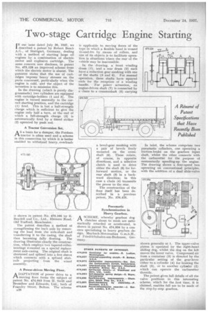
A Tractor Conversion Set
AS a basis for a dumper, the Fordson tractor is often used and a scheme in this connection by which it is better enabled to withstand heavy., overloadi
is shown in patent No. 475,166 by E. Boydell and Co., Ltd., Elsinore Road, Old Trafford, Manchester.
The patent describes a method of strengthening the back axle by removing the load from the axle-shaft and transferring it to the Casing, the shaft then becoming fully floating. The drawing illustrates clearly the construction, which employs two tapered-rollerbearings mounted on a special replacement axle-casing. The original shaft is shortened and splined into a free sleeve which connects with a splined stubaxle projecting' from the wheel assembly.
A Power-driven Moving Floor.
A DAPTATION of power drive to a tt moving floor forms the subject of patent No. 474,943 from H. Swift and Bromilow and Edwards, Ltd., both of Foundry Street, Bolton. The scheme
A38 is applicable to moving floors of the type in which a flexible band is wound to-and-fro by means of rollers, and one of its objects is to facilitate operation in situations where the rear of the chicle may be inaccessible.
In the drawing, a front winding drum (1), and a rear drum (2) each have a reduction gear meshing with one of the shafts (3 and 6). For manual operation, these shafts have squared ends for the reception of a winding handle. For power actuation, an engine-driven shaft (7) is connected by a chain to a countershaft (5) carrying a bevel-gear meshing with a pair of bevels freely mounted on the crossshaft (6). These rotate, of course, in opposite directions, and a selective clutch is used to drive either the shaft (6) for forforward motion, or the rear shaft (3) in a backward direction; in this case a chain (4) transmits the power to the rear.
The construction of the floor itself has been described in a previous patent, No. 376,425.
Pneumatic Synchronization in Heavy Gearbox.
ASCHEME, whereby gearbox dog clutches about to mesh are automatically retarded or accelerated, is shown in patent No. 474,934 by a con
• cern specializing in heavy gearbox design, Maybach-Motorenbau G.m.b.H., of Friedrichshaicn-am-Bodensee, Germany. In brief, the scheme comprises two pneumatic cylinders, one operating a friction-brake on the gearbox input shaft, whilst the other connects with. tin carburetter for the purpose of momentarily speeding-up the engine. The drawing shows a four-speed box operating on conventional principles, with the addition of a dual slide-valve shown generally at 1. The upper-valve piston is operated by the right-hand sliding dog, whilst the dog on the left moves the lower valve. Compressed air from a container (3) is directed by the particular setting of the gear-lever either to a cylinder (4) for braking the shaft (5), or to another cylinder (2) which can operate the carburetter throttle.
The patent gives full details of all the valve positions in this interesting clietne, which for the first time, it is claimed, enables full use to be made of the step-by-step gearbox.