


Gas Producer With Variable' Tuyere Position S UGGESTIONS in respect of
Page 34
If you've noticed an error in this article please click here to report it so we can fix it.
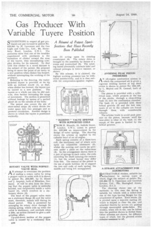
gag producers are put forward in patent No. 523,041 by H. Lawrence and the Gas Light and Coke Co.. Ltd., 84, Horseferry Road, London, S.W.1. The patentees state that one of the troubles experienced with producers is the formation of clinker around the nose of the tuyere, thus necessitating complex devices for its removal. To deal with this clinker in a novel manner is the subject of the patent, the proposal being to move the point of air entry to a new position when clinker has formed, without interrupting the working of the producer.
Referring to the drawing, the waterjacketed tuyere is provided at its tip with an inclined nozzle (1), so that, when clinker has formed, the tuyere can be turned to a new position. The tuyere as a whole can also be slid endwise, thus further increasing the range of movement. The motion is permitted without leakage by means of a packed gland (2) on the outside of the body.
The patent also covers the use of sheet-metal strips (3) which divide the water space into two passages and so promote circulation. Another design is shown in which the tuyere is positioned vertically.
ROTARY VALVE WITH POPPET. VALVE SEAL
AN attempt to overcome the problem of sealing a rotary valve by using a poppet valve in series with it is shown, in patent No. .523,097, by 0. Kiesel and J. Arquint, both of Milnchen, Germany. It will be seen from the draw, ing that the poppet valve is centrally located, and reciprocates inside a valve barrel (4), which revolves in a stationary sleeve (3).
The head of the poppet valve seats on a stationary flange (5) and the valve must, therefore, remain still during its closed period. This is permitted by arranging its rotary drive through its closing spring, which coils up when the valve is stationary, and unwinds when it lifts, an action claimed to give a selfgrinding effect.
Up-and-down motion of the poppet valve is caused by a stationary face cam (1) acting upon its rotating counterpart (6). The rotary drive is brought to the assembly by means of a worm and wormwheel (2). The rotating barrel alternately connects inlet and exhaust passages in known manner, as shown.
By this scheme, it is claimed, the highest working pressures 'tan be withstood satisfactorily, and it is thus suitable for compression-ignition engines.
" HAIRPIN " VALVE SPRINGS WITH SUPPORTED COILS
E.ROM H. Ricardo, 21, Suffolk Street,
London, S.W.1, comes in patent No. 522,998 an improvement in the design of valve springs. The drawing shows the scheme as applied to the cylinder head of an oil engine.
Each spring consists of a three-turn coil, the stationary end of which rests upon an adjustable abutment (2), whilst the moving end exerts its pressure under a plate on the valve-stem (3). In the arrangement shown. there is a pair of springs to each valve, the coils encircling the shaft carrying the rockers (1), but the actual layout may differ from this. The essence of the patent is the use of guide bobbins (4) to support the two end coils of each spring, the middle coil being left unsupported.
AVOIDING PEAK PISTON PRESSURES
AN oil-engine combustion' system in which the compressed air is given a vigorous swirling motion at top dead centre is shown in patent No: 523,137, by L. Meyrol and H. Garaud, both of Paris.
The piston is provided with a cylindrical nose, which projects at the top of the stroke, through a close-fitting bush (1) into the combustion chamber. The bush (1) is provided with three helical grooves (2) and the last remnants of air in the cylinder are forced through these with considerable velocity.
The scheme tends to avoid peak pressure on the piston, because, until the nose-piece is clear of the bush (1) the escape of the gases is limited by the helical grooves.
A STRAKE ATTACHMENT FOR AGRIMOTORS
D ETRACTABLE shakes, suitable for IN.attachment to various types of wheel, fop the subject of patent No. 522,864 by S. Opperman and Ganwick Estates, Ltd., 70a, Basinghall Street, London, E.C.2.
The drawing shows one of the methods; in this case the fitting is suitable for wheels with a rolled-steel rim of the type having flanges for the attachment of spokes. Each strake (3) is pivoted upon a separate casting (2) which is shaped to clear the rim, and attached thereto by screws (1) passing through unoccupied spoke-holes. The strakes, when not in use, can be folded into the position shown in dotted lines.' Other schemes are shown, for different types of wheel, but the pivoted strake remains common to all.