


An Automatic Gearbox
Page 60
If you've noticed an error in this article please click here to report it so we can fix it.
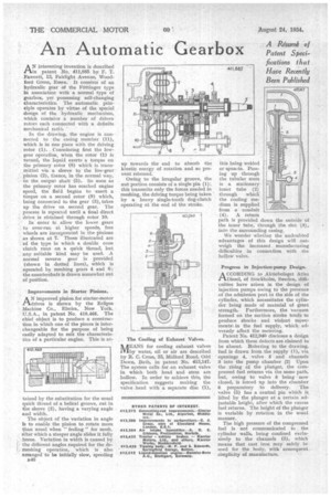
A Re,sionh of Patent Spedfications that Have Recently Been Published AN interesting invention is described in patent No. 411,885 by F. T. Fawcett, 13, Fairlight Avenue, Woodford Green, Essex. It consists of an hydraulic gear of the Fottinger type in association with a normal type of gearbox, yet possessing self-changing characteristics. The automatic principle operates by virtue of the special design of the hydraulic mechanism, which contains a number of driven rotors each connected with a definite
mechanical ratio. • " In the drawing, the engine is connected to the casing member (11), which is in one piece with the driving rotor (1). Considering first the lowgear operation, when the rotor (1) is . turned, the liquid exerts a torque on the primary rotor (8) which is transmitted via a sleeve to the low-gear ' pinion (2), thence, in the normal way, • to the output shaft (5). So soon as the primary rotor has reached engine speed, the fluid begins to exert a torque on a second rotor (9) which, being connected to the gear (3), takes up the drive on second gear. The • process is repeated until a final direct drive is obtained through rotor 10.
In order tc allow the lower gears . to over-run at higher speeds, free wheels are incorporated in the Pinions s shown at 7.. Those illustrated are of the type in which a double cone clutch runs on a quick thread, but any suitable kind may be used. A normal reverse gear is provided (shown in dotted lines), which is operated by meshing gears 4 and 6; the countershaft is drawn somewhat out of position.
Improvements in Starter Pinions.
AN improved pinion for starter-motor drives is shown by the Eclipse Machine Co„ Elmira, New York,
• :U.S.A., in patent No. 410,465. The chief object is to produce a construction in which one of the pieces is interchangeable for the purpose of being easily adapted to suit the characteristics of a particular engine. This is at tained by the substitution for the usual quick thread of a helical groove, cut in the sleeve (2), having a varying angle and width.
The object of the variation in angle is to enable the pinion to rotate more • than usual when "feeling" for mesh, after which a steeper angle slides it fully • . home. Variation in width is caused by the different angles required for the de:. meshing operation, 'which is also arranged" to be initially slow, speeding rs46 up towards the end to absorb the kinetic energy of rotation and so prevent rebound.
Owing to the irregular groove, the nut portion consists of a single pin (1); this transmits only the forces needed in meshing, the driving torque being taken • by a heavy single-tooth dog-clutch operating at the end of the stroke.
The Cooling of Exhaust Valves.
MEANS for cooling exhaust valves by water, oil or air are described by R. C. Cross, 33, Miclford Road, Odd Down, Bath, in patent No. 413,147. The system calls for an exhaust valve in which both head and stem are hollow. In order to achieve this, the specification suggests making the valve head with a separate disc (1),
this being welded or spun-in. Passing up through the tubular stem is a stationary inner tube (2) through which the cooling medium is supplied from a conduit (4). A return path is provided down the outside of the inner tube, through the slot (3); into the surrounding casing.
We wonder whether the undoubted advantages of this design will out weigh the increased manufacturing difficulties in connection with the hollow valve.
Progress in Injection-pump Design.
A CCORDING to Aktiebolaget Atlas 1-1..Diesel, of Stockholm, Sweden, difficulties have arisen in the design • of injection pumps owing to the presence of the admission port in the side of the cylinder, which necessitates the cylinder being made of material of great strength. Furthermore, the vacuum formed on the suction stroke tends: to produce shocks and violent movements.. in the fuel supply, which adversely affect the metering.
Patent No. 412,940 discloses a design from which these defects are claimed to be absent. Referring to the drawing, fuel is drawn from the supply (1), via openings 4, valve 5 and channels 3 into the pump chamber (2) Upon the rising of the plunger, the compressed fuel returns via the same path, but, owing to valve 5 being now closed, is forced up into the chamber 6 preparatory to delivery. The valve (5) has a central pin which is lifted by the plunger at a certain adjustable height, after which the excess fuel returns. The height of the plunger is variable by rotation in the usual manner.
The high pressure of the compressed • fuel is not communicated to the cylinder walls, being confined exclusively to the channels (3), which means that cast iron may safely be used for the body, with consequent simplicity of manufacture..