


For DRIVERS, MECHANICS & FOREMEN.
Page 21
If you've noticed an error in this article please click here to report it so we can fix it.
A PIZIZE OF TEN SIAILLINGS is awarded each week to the sender of the best letter whichWe publish on this page ; all others are paid for at the rate of-es penny a line, with an allowance for photcgkaplis. All notes are edited before being published, Mention your employer's name, in confidence, as evidence of good faith. Address, D., X. and F., "The Commercial Motor," 7-15, flosebery Avenue, London, E.G. .1.
Lamps Alight.
On Saturday, April 26th, light your lamps at 8.41 in. London, 9.36 in Edinh,urgh, 8.56 in Newcastle, 9.3 in Liverpool, 8.49 in Birmingham, 8.51 in Bristol, and 9.36 in Dublin.
Keyway Cutting Machine.
The sender of the following communication has been . awarded the i0s. prize this week,.
[1965] "H.M." (West Bromwich) writes :—"Recently I came across an interesting device for cutting splines in gearwheels. It is useful for any number of splines, provided a suitable jig, which I will describe, is made for each new arrangement of keyways. The a,ccom
partying sketch [Which we have had re-drawn.—En.] shows a job set, cutting six splines in a gearwheel, the machine used being an ordinary keyseater.
The splines, of course have to be carefully and correctly spaced, and the course, thing to do was to make a jig to enable this to be effected. For this purpose a block similar to that shown in Fig. 2 was 'made. The outside diameter is equal to the bore of the gearwheel. Five keyways are cut round the outside of this plug, as shown, and one slot is cut right through to a little past the centre of the plug. In operation, the plug is dropped into the gearwheel which requires to be splined, as shown in the main figure. The broach, is made of Monarch air-hardened steel of the right thickness for the keyway and of such a depth that its back edge bears up against the groove in the plug. When one keyway is cut; the bush is turned round one-sixth of a turn, and a tightlyfitting key is inserted in one of the keyways of the plug and in the spline already cut in the gear. This correctly positions the slot in the plug for the insertion of the tool to cut the second keyway. This process is repeated until the whole six keyways are finished. "I may add that several hundreds of gears have been cut by this method with every satisfaction."
Replacing a Valve Guide.,
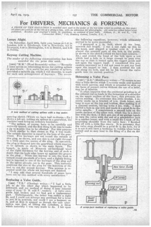
11966J " T.B." (Chorley) writes :—" I had a little job to do the other day which happened to be awkward, and my method of doing it may interest some of your D. M. arid F.' readers. valve stem guide had broken and we had got a replacement part. ' Unfortunately, the latter was rather a tight ,fit, and I could not arrange any purchase for a lever to put it in position, nor could I use a hammer on it, and at first it seemed as though the on17 alternative was that of lifting the cylinders, a thing which naturally I was very loath to do. I hit upon
the following expedient, however,' which ultimately proved to be quite successful.
"I procured a / in. bolt, about 3/ ins. long, screwed full length. I ran a nut right up this to the head, and slipped a washer over it. I then placed the screwed part of the bolt in the guide, as shown in the sketch [which we have had redrawn.— ED.] and rested the head of the bolt upon a, nut which had a hole in it large enough • to pass over the top so that it rested upon the tappet guide and not upon the tappet itself. I considered this precaution necessary as I did not want to put any load upon the tappet or cam I then screwed the nut out along its bolt, and bit by bit forced the valve guide into its correct position."
Skimming a Valve Face.
[1967] " B.D." (Middlesex) writes :—" It occurs to me that a, little device which I recently made and applied with much success, and which is intended to skim up the faces of poppet valves 4-ithout the -use of a lathe, may be of interest. It often happens that the continual grinding-in of the exhaust valves leads to the formation of a shoulder on the upper surface of the face; this prevents the valves seating. To overcome this little trouble, I recently made up a bracket of /-in. thick brass, and bent it over at the top and bottom, thus making it of a channel section, having webs 2 ins. wide.. I the drilled a hole in one web and made it a good fit to the valve spindle. . I countersunk a second hole on the inside surface of the other web, which was in a direct line with the first. then got one of my garage hands to turn the valve with the aid of a screwdriver held in a ratchet brace, and with a small file I took off the projecting shoulder from the valve face ; I finished this off with a little fine emery. It is necessary that the valve stem should be a good fit in the hole, for if it is not it will have a tendency to wobble when being turned and so may lead to the filing of a flat on the seat."