


A 'Low-compression Oil Engine
Page 58
If you've noticed an error in this article please click here to report it so we can fix it.
IT is usual to design oil engines for a high compression ratio with a view to reducing the time lag between injection and self-ignition. The ratio employed is usually higher than is strictly necessary for the efficient functioning of an engine and it is desirable
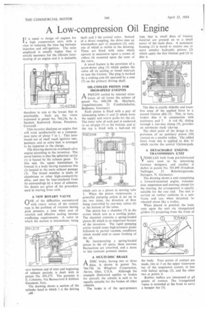
therefore to aim at the lowest that is practicable. Such are the views expressed in patent No, 704,236, by A. Sanders. Redinnick House, Penzance, Cornwall. • This inventor discloses an engine that will work satisfactorily on a compresSion ratio of about 7 to 1, This ratio Would not of itself reach ignition temperature, and so extra heat is arranged to be_ imparted to the charge. The drawing shows an overhead-valve engine atcording to the invention. The novel feature is that the spherical cavity (1) is heated by the exhaust gases. To this end, the upper hemisphere is formed in a body having numerous fins (2) located in the main exhaust passage (3). The .finned member is made of aluminium or other high-conductivity alloy, and may be heat-insulated from its surroundings by a layer of asbestos. No details are given of the procedure used in starting from cold.
A NEW ROTARY VALVE
nNE of the difficulties encountered
with rotary valves of the conical type is the problem of rotation during peak pressure, a time when ease of rotation and effective sealing become conflicting requirements. A valve in which the motion is intermittent, being zero between end of inlet and beginning of exhaust periods, is dealt with in patent No. 691,275. The. patentee is E. Colombo, Via Buonarrotti 8 Abbiate Guazzoni, Italy.
The drawing shows a section of the lylinder head in which 1 is the driving A40 • shaft and 2 the conical valve. Instead of a direct coupling, the drive uses an intermediate pair of members (3), only one of which is visible in the drawing. These are fitted with cams which operate in succession upon a crown of rollers (4) mounted upon the stem of the valve.
A novel feature is the provision of a screw-down plug (5) which pushes the valve off its seating at timed intervals to ease the friction. The plug is worked by a rocking arm (6) operated by a cam (7) on the primary driving shaft.
OIL-COOLED PISTON FOR HIGH-SPEED ENGINES
A PISTON cooled by internal circu lation of oil forms the subject of patent No. 690,298 (K. Maybach, Zeppelinstrasse, 21 Friedrichshafen, Bodensee, Germany).
Each piston is fitted with a pair of telescoping tubes (I and 2) which form the supply and return paths for the oil. The inner tube of each pair is anchored. to an oil-pipe (3) at the bottom, and at the top is fitted with a ball-end (4) which acts as a piston in moving tube 5. When the piston reciprocates, a powerful, pumping action is set up in the two tubes, the direction of flow being controlled by one-way valves (6) at the bottom of the tubes.
The piston has a chamber (7) in the crown which acts as a cooling jacket. The chamber contains a spring-loaded piston (8) which is an important feature of the invention. The rapid pumping action would cause high-pressure peaks followed by partial vacuum, conditions which would tend to cause frothing of the oil.
By incorporating a spring-loaded piston in the oil space, these extreme fluctuations are absorbed, and a more or less constant pressure ensues.
A MULTI-DISC BRAKE
ADISC brake, having two or three discs, is shown in patent No. 704,730, by Wingfoot Corporation,
Akron, Ohio, U.S.A. Although the example illustrated applies to brakes for aircraft, the scheme is said to be equally suitable for the lirakes of other vehicles.
The brake is of the spot-pressure type, that is, small discs of friction material are pressed on to a small sector of the main discs. A stationary housing (1) is bored to receive one or more annular hydraulic pistons (2) which apply the first friction pad (3) to disc 4.
The disc is axially slidable and transfers some of the applied force to a second friction pt,ci (5). This, in turn, brakes disc 6 in conjunction • with stationary pad 7. A rod (8), sliding through a one-way clamp (9), provides an automatic slack take-up.
The chief point of the design is the provision of an auxiliary piston (10) located on a smaller radius. The added force from this is applied to disc 11 which carries the central friction-pads.
A DETACHABLE ENGINETRANSMISSION UNIT VEHICLES built from pre-fabricated units seem to be interesting German designers, and another is shown in patent No. 705,490 (Friedrich
Nallinger, 22 Relenbergstrasse, Stuttgart, N. Germany).
The drawing shows a unit comprising a forward-mounted engine, transmission, suspension and steering; except for the steering, the arrangement is equally suitable for the rear end. The unit is carried on rubber cushions in a subframe and can, when detached, be wheeled about like a trolley.
When placed in position the body rests upon the unit via triangulated girders (1) projecting from the front of he body. Four points of contact are made, two at 3 on the upper transverse 'air of the suspension system, in line with helical springs (2), and the other two at points 4.
Rubber buffers are interposed at 411 points of contact. The triangulated frame is extended at the front to carry a bumper bar (5).