


A Freely Mounted
Page 72
If you've noticed an error in this article please click here to report it so we can fix it.
FRONT AXLE
A Resume of Recently Published Patent Specifications
AN arrangement which permits a front axle to ..tilt in either direction to enable a vehicle to travel over uneven ground, is described in patent No. 333,663 by C. Dexter, of 154, Poplar Road, Edgbastou, Birmingham.
Long horizontal flexible springs are used as a means for determining the position of the axle, but they are not of sidlicient stiffness to support the weight of the .vehicle. Brackets depending from the frame behind the dumbirons carry bellcranks which transmit movement to a cross-spring pivotally mounted at its centre to a cross-member. ended connecting rods are employed to connect the parts.
A Centrifugal Clutch.
Czecho-Slovakia comes the patent of K. Vondra, of 183 Kysperk nad Orlici, No. 333,694. This relates to a clutch which is centrifugally controlled so that frictional con members rotates
The specification is a long one, of applications of the plan. In the example we have selected, 2 is the driving member, whilst 1 is the driven. The plate (4) Is connected to the shaft by means of a cotter pin. The cotter (50) holds the friction
disc (6) to the shaft. Certain members (3) and (4) are provided with teeth (23), the driving direction of which is against the wedging faces so that when power is transmitted 3 is forced into .frictional contact with 2, and by pressing it against 6 the drive is obtained.
A catch (7) is held towards the shaft by a spring (12) which, so long as it is in the position shown, will not permit member 3 to advance towards2, but when a predetermined speed is attained the catch flies outward, thus allowing engagement to take place.
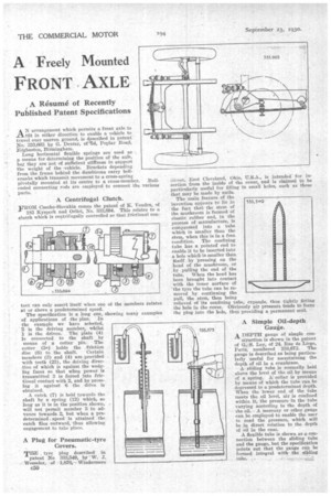
A Plug for Pneumatic-tyre Covers.
THE tyre plug described in patent No 333,549, by W. J.
• Wesseler, of 1,876,' Windermere treet, East Cleveland, Ohio, U.S.A., is intended for insertion from the inside of the cover, and is Claimed to be particularly useful for filling in small holes, such as those that may be made by nails. The main feature of the invention appears to lie in the fact that the stem of the mushroom is formed of elastic rubber and, in the procesS of manufacture, is compressed into a tube which is Smaller than the stem, when this is in a free condition. The confining tube has a pointed' end to enable it to he inserted into a hole which is smaller than itself by pressing on the head of the mushroom, or by .pulling the end of the tube. When the bead has been brought into contact with the inner surface of the tyre the tube can be removed by continuing the pull, the stem, then being relieved of its confining tobe, expands, thus tightly fitting the hole in the cover. Obviously air pressure tends to force the plug into the hole, thus providing a permanent seal. 533,54-9
r ,
A Simple Oil-depth Gauge.
A DEPTH gauge of simple con struction is shown in the patent of C. S. Loy, of 24, Rue de Liege, Paris, numbered 333,873. The gauge is described as being particularly useful for ascertaining the depth of oil in a crankcase.
A sliding tube is normally held above the level of the oil by means of a spring. A collar is provided by Means of which the tube can be depressed to a predetermined depth. When the lower end of the tube meets the oil level, air is confined within it, the pressure in the tube varying accOrding to the depth of the oil. A mercury or other gauge can be employed to enable the user to read the pressure, which will be in direct relation to the depth of oil in the case.
A flexible tube is shown as a connection between the sliding tube and the gauge, but the specification points out that the gauge can be formed integral withthe sliding tube.