


Patents Completed,
Page 22
If you've noticed an error in this article please click here to report it so we can fix it.
Complete specifications of the following patents will be sent to any address in the United Kingdom upon receipt of eightpence per copy at the Sale Branch, Patent Office, Holborn, W.C.
SOLDERING FLUX.—.Teffery.—No. 8,272, dated 6th April, 1909.—This invention relates to soldering flux for use in soldering aluminium. This flux consists of one part of sal-ammoniac, three parts of glycerine and four parts of water, the whole being heated to boiling point. The method of application is as follows :--The soldering iron should be tinned in the usual manner and the solder after being dipped in the flux should be melted on the point of the iron. The solder is then rubbed on the part to be soldered by the iron.
IMPROVED VALVE GEAR.—The Albion Motor Car Co., Ltd., and Another.—No. 23,082, 30th October, 1908.—This valve gear is of the piston valve type and comprises piston valves, one for the inlet and one for the exhaust, situated in cylinders parallel with the engine cylinder. The valves are operated from the main shafting by spur.gearing, which drives auxiliary shafts situated parallel to the main shaft. These shafts have cranks therean from which the piston-valve connecting rods are driven. The piston valve itself has an upwardlyprojecting portion within which ports are situated. These ports open into an annular port which connects with the main cylinder. Above this annular port is situated an L-shaped piston ring with outwardly-projecting flanges which are held between the top and bottom of the valve cylinder. This ring embraces the piston to prevent leakage.
IMPROVED MEANS OF SUPPORTING AUTOMOBILE FRAMES.—The Wolselev Tool and Motor Car Co., Ltd., and A. 'A. Remington.—No. 18,149, 29th August, 1908.—In this method of supporting automobile frames one end of a, laminated spring is pivotally connected to a link which is, in turn, pivoted to a
radius bar. This radius bar serves to maintain the axle in a substantially-constant position, in relation to the frame, endwise thereof, and is rigidly connected at its rear end with the axle bearing, its other end being pivoted at a point about which the spring also turns. In order to adjust the height of the frame in relation ti the axle, the other end of the spring is pivotally connected to a link formed in two parts, one of which is arranged to screw in and out of the other. The lower member of this link is carried on a bracket which allows longitudinal movement of the spring only.
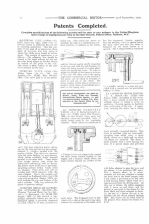
AN IMPROVED THROTTLE VALVE.—E. J. Y. Rutherford and C. A. Ross.—No. 21,969, dated 17th October, 1908.—In this throttle valve, main and auxiliary valves are provided, both of which control ports in the regulating chamber. These valves are connected to a T-shaped lever and respectively control the main steam conduit leading to the engine and a by-pass which enters the main conduit beyond the control of the main valve. The T-shaped lever is provided with a slot at the end of one arm, wherein the connection to the main valve has free movement, thereby ensuring that the auxiliary valve is opened before the main valve and that the latter is balanced by the steam before it is opened. The T-shaped lever is connected to a spindle carried in a boss and provided with a conical seat for preventing leakage of steam.
AN IMPROVED MOTOR PLOUGH. —L. A. Hubert.—No, 17,318.-18th August, 1908.—According to this invention, a motor plough is provided with multiple shares to which is given an oscillating vibrating motion to facilitate their penetration of the soil. A framework carrying the motor has a tilting frame pivotally connected thereto. This frame is provided with two rearwardlyextending arms which carry a drum which rotates on a shaft and on which the shares are mounted. The drum is made integral with a lever having two arms of a special shape and provided with holes adapted to stop the lever and the shares, in two positions 180° apart. This is brought about by a screwthreaded rod and nut, adapted to render the front arm of the lever integral with a rod which is provided at its end with a fork having rollers which work on a cam operated from the driving gear. As this cam is driven, the rollers engaging with it move up and down, and the motion is conveyed to the shares by the lever, shaft and drum referred to above. At the end of a furrow the nut is unscrewed and the shares rotated through 180°. The shares can be lifted clear of the ground when desired by means of a, lever.