


Progress in Rotary-valve Design
Page 62
If you've noticed an error in this article please click here to report it so we can fix it.
A Resume of Recently Published Patent Specifications That Are Obtainable From the Patent Office, Price ls. Each
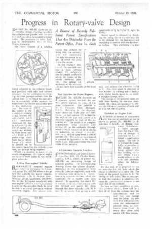
PATENT No. 453,331 shows an unorthodox design of engine, in which the cylinders are parallel with the central shaft on which is mounted a rotary valve. The patentees are Alvis, Ltd., and G. Smith-Clarke, both of Alvis Works, Coventry.
The valve consists of a rotating
barrel adjacent to the cylinder heads, and provided with inlet and exhaust passages. In the accompanying drawing the inlet passages radiate from the central bore (4) to which the carburetter is connected, whilst separate_ exhaust bores (2) lead to an annular port in the stationary part. The basis of the patent is the method of forming a seal between the valve-barrel a n d t h e. combustion chambers (5); this is achieved by the use of bushes (3), which are slidable in their bores and are fitted with piston rings. Each bush has a curved flange (1), which is pressed on to the rotary barrel by the cylinder pressure, no springs being required.
Whilst no mention is made of the crank arrangement, this type of engine would lend itself easily to the swathplate principle.
A New Rear-engined Vehicle.
REARWARDLY mounted engines are definitely increasing in favour, and patent No. 453,388 shows a design specially suitable for heavy vehicles. The inventor is Sir H. Nugent, Bart., Windsor House, T.ambourn, Berkshire. One of the difficulties associated with rear-engined vehicles is to find sufficient length for the propeller shaft, in order to obtain universal movement without excessive angles. The patent over
comes this problem by using only one universal joint and constraining the axle movement to an arc, of which the joint forms the centre.
In the example illustrated, the rear-axle casing is held between clamps (1) sufficiently free to permit oscillation about the centre of the sturdy Universal joint
(2) The springs are 453.174 anchored at the rear end
(3) and have their shackles at the front end.
. Fuel Injection for Petrol Engines.
DATENT No. 453,274 describes an
injection system intended for use with petrol engines, in place of the usual carburetter. The patentee is M. G. Chandler, Flint, Michigan, U.S.A. Referring to the drawing, which shows an intake pipe and inlet valve, the fuel injector (1) is fixed in the wall of the pipe and points in a direction opposite to that of the incoming air. The nozzle is of complex construction, being provided with orifices (3) on the underside through which a small amount of air is drawn by induction, to emerge a moment later as an air-fuel spray from a conical annulus (2). The mixture thus formed is sprayed in opposition to the movement of air. This point forms the chief claim of the patentee.
A Close-ratio Epicyclic Gearbox,
FROM Mechanical and Genera) Inventions Co., Ltd., 10, Charles Street, London, S.W.1, comes, in patent No. 453,174, an interesting design of epicyclic gearbox. The accompanying drawing shows the scheme diagrammatically; in this arrangement three epicyclic units are employed, each with a reduction ratio of 14 to 1. Operation is by separate clutches, which are controlled by a master cam (not shown). In operation, the clutch (1) is moved to the left ; this engages with the flywheel and passes the drive through the three epicyclic units (6, 5 and 4) in series, thus giving a first speed ratio of 11 by 14 by 14, equal to 3.375. '
Second speed is obtained by clutching the casing (2) of the first unit (6) to the element (1), the last-mentioned remaining in contact with the flywheel, as before. This eliminates the first unit, and reduces the reduction to 2* to 1. The third speed is obtained in like manner by cutting out a further unit, whilst fourth speed is, as usual, a straight-through drive.
The casings of the epicyclic units are held from turning by one-way abutments (3) ; these are necessary to permit the full-speed rotation of each unit as it is cut out of action.
Coal-dust as Engine Fuel.
ASCHEME of interest in connection with the use of coal-dust as fuel is shown in patent No. 452,608 by F. Schichau G.m.b.H., of Elbing, Germany. It deals with a valve arrangement for the -admission of charges of coal-dust to an internal combustion engine. The aim is to prevent the possibility of portions of the charge from being ejected into the working cylinder, where they would adhere to the walls and adversely affect the lubrication.
To this end it is proposed to use an ante-chamber (2) into which the charge is admitted by a valve (1). The basis of the patent appears to be the timing of this valve; this is arranged so that the coal-dust is admitted only when the ante-chamber pressure is less than that of the cylinder.
So long as these conditions of relative pressures obtain, there will be a flow of air from the cylinder into the ante-chamber, and no coal dust can emerge from the latter. An outward flow will occur only when the ante-chamber pressure rises, as combustion takes place. It seems that some solid matter will then eseape.