


A Power-driven Wheelbarrow
Page 52
If you've noticed an error in this article please click here to report it so we can fix it.
TO mechanize the numerous minor transporting jobs on a building site is the primary object of a small vehicle shown in patent No. 657,593, by Winget, Ltd., Rochester, Kent. The machine can best be described as a power-driven wheelbarrow, the, driver walking with it and driving it by simple controls.
Referring to the drawing, the frame , is A-shaped in plan, having a pair of large wheels (1) at the front and a single driving wheel (2) at the rear. Instead of a single wheel a closecoupled pair can be used at this end. A 2 h.p.,petrol engine is geared down 50 to I to drive the wheel, and the whole unit can be swivelled through a full turn to give a reverse. • A steering. wheel (3) is used for this purpose, and this also forms the clutch and brake control. By tipping the wheel downwards to position 4, the brake is released, the engine accelerated and the clutch engaged, so that driving is reduced to its simplest terms. By releasing the wheel, the vehicle is brought to a stop with the engine idling. The barrow portion (5) is made to tip forward as shown in broken line.
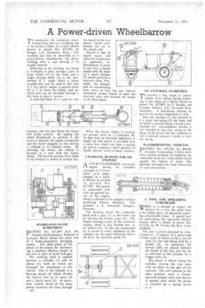
DATENT No. 657,899 (S.A. des 11. Anciens Etablissements Panhard et Levassor, Paris) shows the basic unit of a hydro-pneumatic springing system. The chief point of the patent is the means for maintaining a constant effective length of the unit in spite of small leakages.
The working load is applied between a cylinder (1) and its piston (2), both of which are arranged for attachment to the vehicle. Also in the cylinder is a floating piston (3) which divides the interior into an air space (4) and a liquid space (5). In operation, inward thrust of the main piston transmits the force through A42 the liquid to the free piston, which compresses the air in the closed end.
Should a loss of liquid occur, and allow the two pistons to apptoach, replenishment is made in this way; a liquid supply-port (6) leads to a small plunger (7) which contains a one-way valve. Normally, the plunger and its surrounding bore move as one, but any relative movement causes liquid to pass the one-way valve and increase the length of the fluid space. • When the correct length is reached, the plunger seals on a valve-face (8). To deal with an abnormal deficiency of liquid, the free piston is provided with a valve face which can meet a seating (9) and by trapping a small quantity of liquid, prevent metal-to-metal hammer.
CHARGING BLOWER FOR OIL ENGINES
A FOUR-CYLINDERED two-stroke engine having its cylinders
arranged in V-formation a n d supercharged by a builtin blower, is covered in patent No. 657,595. The patent is concerned only with the general' layout of the engine, which is claimed to be compact without sacrificing blower efficiency. The' patentee is A. Schnuerle, Stuttgart, Germany.
The drawing shows the crankshaft fitted with a gear (I) at the front end for driving the blower rotor (2). The blower housing is part of the crankcase casting; which is also formed into an air receiver (3). In this, the compressed air is stored to await admission to the cylinders via the usual wall-ports. Gears (4) drive the injection pump (5).
6575)4 47, At7,1 1 1 k
" • 9,
0